
A capacitor is an electronic component that can store electric charge. When a capacitor has a stored electric charge, it will have a voltage difference across its terminals.
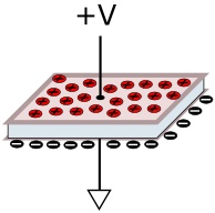
A capacitor is constructed with two conductive plates separated by an insulator called a dielectric. When a capacitor is connected in series with a DC voltage source, a current flows through the circuit, charging up the capacitor.
The amount of charge a capacitor can store depends upon the size of its plates, the separation between the plates, and the material of the dielectric insulator. The larger the plates, the more charge it is capable of storing. And the smaller the separation between the plates, the higher the Capacitance value will be. The capacitance is given by the formula;
C = Q / V
Where Q is the amount of charge and V is the voltage applied across it. The unit of measurement for capacitance is the Farad. A capacitor has a value of 1 Farad when it holds a charge of 1 Coulomb when one volt applied across its terminals.
Capacitor with DC
Let's consider how a capacitor reacts to DC. Assuming that initially the capacitor is in the discharged state, there will be zero voltage across its plates. When DC voltage is applied across its terminals, current flows and charges it.
The initial flow of charging current through the capacitor will be high. As charging current flows, a positive charge will built up on one plate and a negative charge on the other plate.
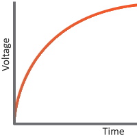
As the charge across the capacitor continues, the voltage developed resists the flow of more charges. The charging current is gradually reduced as the charge accumulation on its plates resists the flow of current. The charging current continues to flow until the voltage developed across the capacitor equals voltage applied across it. At this point the charging current ceases to flow and the capacitor is fully charged. The capacitor will hold this voltage while the voltage is applied across it.
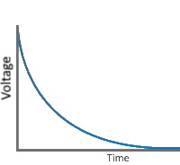
If the voltage applied across the capacitor drops to zero, as long as there is a complete circuit path, discharging current from the capacitor will start flowing. This discharging current will cause the voltage across the capacitor to start dropping. The discharging current decreases as the charge across the capacitor drops. After some time the capacitor voltage will reach zero. The capacitor is returned to the discharged state, there will be zero voltage across its plates.
Capacitor with AC
When DC voltage is applied to a capacitor it charges in only one direction. After the capacitor is fully charged, it blocks the flow of current. When AC is applied to a capacitor, it alternatively charges and discharges depending on the frequency. Therefore current will continue to flow through a capacitor indefinitely.
The charging current and discharging current through a capacitor subjected to AC depends on the voltage and the frequency of change of the voltage applied across it.
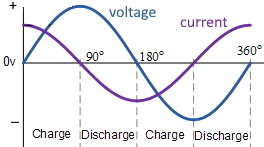
Study the graph shown above. When AC voltage is first applied across a capacitor, initial voltage will be minimum and at this instant charging current will be at maximum. When voltage reaches its peak value charging current will be zero. After reaching its peak value, voltage will start to decrease and discharging current will start to flow from the capacitor. When the AC voltage reaches zero, completing the positive half cycle of the cycle, discharging current will be at maximum. Once the negative cycle starts, discharging current gradually begins reducing. Current reaches zero once the voltage hits lowest value in the negative half cycle.
When AC is applied to a capacitor, current flow leads the voltage by 90°. Or to say it another way, in AC circuits Voltage lags Current by 90°. This is stated as voltage and current being out of phase.
Capacitive Reactance
Much as resistors present resistance to the flow of current in DC circuits, capacitors present resistance to the flow of current in AC circuits. This is resistance is called reactance, and more specifically capacitive reactance. Capacitive reactance has units of ohms, and is given by the formula:

From the formula we can see that capacitive reactance decreases with increase in the frequency of the AC signal and with the capacitance of the capacitor. When the signal frequency is high, reactance will be low. At a certain frequency, a capacitor acts like a conductor.
Capacitive Timing Circuits

When using a capacitor with DC, it takes time to charge and reach the applied voltage. This characteristic of a Capacitor can be used to generate time delays. A resistor is used along with a capacitor to control the rate of charging and control the time delay.
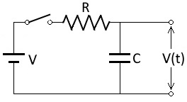
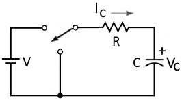
Shown above circuit is a RC timing circuit. A DC voltage is applied to the capacitor through a resistor. The time delay generated in this circuit can be determined by the Time constant, T, of the circuit. The time constant is calculated using the formula:
T = RC
The time constant T (in seconds) of an RC circuit, is equal to the product of the resistance R (in ohms) and the capacitance C (in farads). It is the time required to charge the capacitor, through the resistor, from an initial voltage of 0 to 63.2% of the value of an applied DC voltage. It takes 5 time constants to charge the capacitor to 99.3% of the applied voltage.
Similarly, If a capacitor previously charged to the value of the applied voltage is discharged through the resistor, in one time constant, it will discharge to 63% of the applied voltage. It takes 5 time constants to discharge the capacitor to .75% of the applied voltage.
Real Capacitors
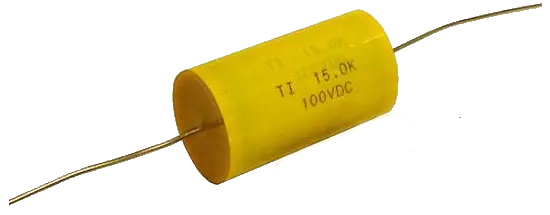
Shown above is a polyester film capacitor. They are constructed of two sheets of aluminum foil alternated with two sheets of polyester film folded or rolled up into the shape of a cylinder. Leads are attached to the aluminum sheets, which act as the capacitors plates. The sheets of plastics are the dielectric.
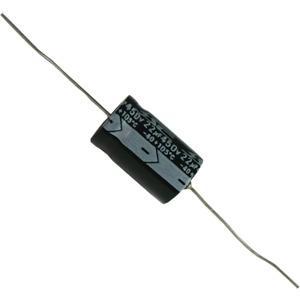
Shown above is an electrolytic capacitor. This type of capacitor uses an gel electrolyte to achieve a higher capacitance. Most electrolytic capacitors are polarized. This means that the voltage on the positive terminal must be greater than the voltage on the negative terminal.
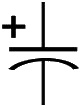
Shown above is the schematic symbol for a polarized capacitor, which differs from the schematic symbol for an unpolarized capacitor by having a curved line on one side and a + symbol indicating its polarity.

