All the amazing things that can be done with electronics are the result of one simple thing - electric charge. Electric charge comes in two forms, positive and negative. A positive charge is the electrostatic field radiated by protons. A negative charge is the electrostatic field radiated by electrons.
The power that comes from electricity is caused by the fact that same charges repel each other and opposite charges attract each other. In other words, two electrons repel each other.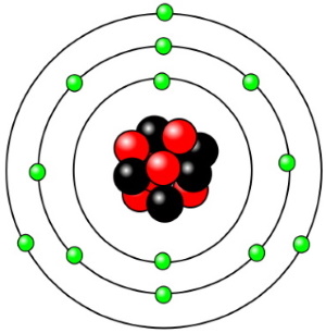
One important fact is that the nucleus of an atom is relatively heavy. That's because a proton is about 1800 times more massive than an electron. The reason this is important is because electricity primarily involves the flow of electrons. The nucleus of an atom generally doesn't move much. The atoms of some elements hold onto their electrons tightly. These elements are called "insulators".
The atoms of some elements, like copper and aluminum, hold onto their electrons loosely, especially the electrons that orbit in the outer shells. It is these electrons that tend to break loose and can be used to create electron flow. Elements that hold onto their electrons loosely are called "conductors".
There is a third type of material, elements like germanium and silicon, that sometimes conduct and sometimes don't, and sometimes conduct some but not fully. It depends on how you treat, or "bias" them. These materials are called semiconductors and they are responsible for much of our modern electronics. But we won't delve into semiconductors in this basic introduction.
There are two basic types of electron flow - direct current (DC) and alternating current (AC). DC current flows in one direction, from a more negatively charged location to a less negatively charged location. Since same charges repel each other, negatively charged electrons will flow in an attempt to get as far away from each other as possible.
The amount of current flowing in a circuit is measured in Amperes (Amps). If you were comparing electron flow to water flow, you might compare amps to gallons. The strength of charge in a circuit is measured in Volts (V). You might compare volts, or voltage, to the pressure of water coming out of a faucet or hose. In AC, the voltage polarity reverses along with the direction of current flow.
One strange thing in electronics is that, although electrons flow from a more negatively charged location to a less negatively charged location, in other words from negative to positive, technicians and engineers always consider current to be flowing from positive to negative. This is because when Benjamin Franklin experimented with electricity, he assumed that the electrical current must be positive. We now understand that electrons have a negative charge, and that the flow of electrons is actually in the opposite direction.
Usually positive is the power source labeled Vcc, and the current is visualized to be flowing to Ground (Gnd), which is defined as zero volts. Strangely enough, this reverse thinking doesn't usually cause any problems in electronic calculations.
One last thing needs to be covered in this basic introduction to electronics. In electronic circuits, there is a resistance to the flow of current. This resistance to the flow of current is appropriately called "Resistance" and it's measured in a unit called "Ohms". There is an equation commonly used in electronics called "Ohm's law" that says E = I x R (volts equals amps times ohms). Rearranging this formula allows you to calculate almost everything you might want to know about a DC circuit.
Electronic Circuits
Work is accomplished in an electric circuit as the result of electron current flow. Current flow is produced by a power source, such as a battery, in the circuit. A power source has a potential difference across it, a voltage, across its terminals. Electrons flow from the more negative terminal to the less negative terminal in an attempt to reduce the potential difference.
A proper circuit has some resistance in it. If the circuit does not make a complete path, it is an open circuit, so no current can flow. If the circuit does not have some resistance in it (zero resistance), it is a Short circuit and current flow will be infinite (or whatever maximum the battery is able to provide).
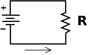
In the above diagram, the symbol on the left is the power source. Let's say the power source has a voltage, or potential difference across it of 10 Volts. Then because the resistor R is connected directly across the power source, it also has 10 volts across it.
Ohm's law
Named after the German physicist Georg Ohm, Ohm's law states that the electrical current flowing through a circuit is directly proportional to the voltage across it, and inversely proportional to the resistance in the circuit.
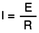
In the formula, Current (measured in amps) is, by convention, represented by the letter I for Intensity of current. Voltage (measured in volts) is represented by E, for Electromotive force, and Resistance (measured in ohms) is represented by R.
Let's say the resistor has a resistance of 100 ohms. The current through the circuit can be calculated by Ohm's law: I = E/R (current in amps equals voltage in volts divided by resistance in ohms). Then the current would be 10/100, or 0.1 amps (100 milliamperes).
Series Circuits
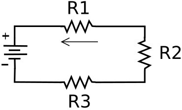
In a series circuit electronic devices or loads are connected in a chain so that current has to pass through every load. Since the loads are in series, the current is the same in all parts of the circuit. That current can be calculated by adding the resistances of all the loads and then using Ohm's law.
Again. let's say the power source is 10 volts. Let's give the resistors values of R1 = 120 ohms, R2 = 100 ohms, R3 = 180 ohms. So the total series resistance would be 400 ohms. Using Ohm's law: I = E/R, I = 10/400. The current would be .025 amps (25 milliamperes).
However, because the loads each have different resistances, the voltage drop across each load is different. The voltage accross each load can be calculated by Ohm's law E = I x R.
The voltage across R1 would be .025 x 120 = 3 volts.
The voltage across R2 would be .025 x 100 = 2.5 volts.
The voltage across R3 would be .025 x 180 = 4.5 volts.
Note that because all three resistors in series are connected accross the 10 volt power source, the sum of the voltage drops accross all the resistors must add up to 10 volts.
Parallel Circuits
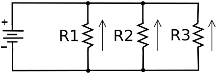
In a parallel circuit devices or loads are each connected separately accross the power source. Since the loads are in parallel, the voltage across each load is the same. However, because because the loads each have different resistance, the current flow through each parallel path, or branch, is different. The current through each path can be calculated using Ohm's law: I = E/R.
Again, let's say the power source is 10 volts. Let's give the resistors values of R1 = 200 ohms, R2 = 100 ohms, R3 = 250 ohms.
The current through R1 would be 10/200 = .05 amps.
The current through R2 would be 10/100 = .10 amps.
The current through R3 would be 10/250 = .04 amps.
Note that the total current through the circuit is the sum of all the currents through the parallel paths; It = .05 + .10 + .04 = .19 amps.
There is an interesting formula to calculate the equivalent resistance of resistors in parallel; the reciprocal of the equivalent resistance is the sum of the reciprocals of the resistances of the parallel resistors.
1/Re = 1/R1 + 1/R2 + 1/R3
So in the above circuit, 1/Re = 1/200 + 1/100 + 1/250 ; 1/Re = .005 + .01 + .004 ; 1/.019 = 52.63 ohms.
Using Ohm's law to calculate the total current through the parallel resistor network, I = E/R; I = 10/52.63, I = .19 amps.
Series Parallel Circuits
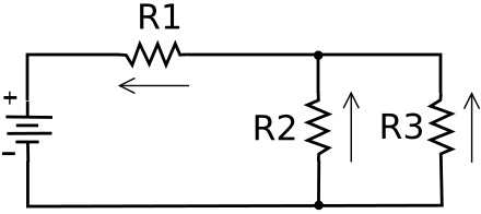
In a series parallel circuit, loads connected in parallel may be connected in series with another load or loads - or - loads connected in series may be connected in parallel with another load or loads. To solve a series parallel circuit you have to calculate the equivalent resistance of a parallel branch, and then use that value as if the branch was a single series load.
In the series parallel circuit above, let's say the power source is 10 Volts. Let's give the resistors values of R1 = 100 ohms, R2 = 200 ohms, R3 = 400 ohms.
Here's how we calculate the various currents and voltages in this circuit:
First calculate the equivalent resistance of the parallel part of the circuit (R2 and R3).
1/Re = 1/R2 + 1/R3
1/Re = 1/200 + 1/400
1/Re = .005 + .0025
1/.0075 = 133 ohms.
The parallel part of the circuit is in series with R1, so the sum of the series resistances is 133 ohms + 100 ohms = 233 ohms.
Using Ohm's law to calculate the total current through the circuit:
I = E/R; I = 10/233; I = .043 amps.
Using Ohm's law E = I x R to calculate the voltage drop across each resistor:
E R1 = .043 x 100 = 4.3 volts.
E R2 || R3 (parallel network) = .043 x 133 = 5.7 volts
Now, adding the two series voltage drops: 4.3 + 5.7 = 10.0 volts, the same as power source, so our calculations are correct.
Using Ohm's law, along with the reciprocal formula to calculate the equivalent resistance of resistors in parallel, you can calculate the voltage or current in any part of a circuit.

