Magnetic Force
If a moving electric charge, that is electric current, produces a magnetic field that can exert a force on another magnet, then the reverse should be true by Newton's third law. In other words, a charge moving through the magnetic field produced by another object should experience a force - and this is exactly what we find. As a concrete example, consider the diagram below, which shows a charge q moving with velocity through a magnetic field between the poles of a permanent magnet. The magnitude F of the force experienced by this charge is
F = qvB sin θ
where θ is the angle between the velocity of the charge and the magnetic field.
The direction of the force may be found by using another version of the right-hand rule: First, we join the tails of the velocity vector and a magnetic field vector, as shown in step 1 of the diagram below. We then curl our right fingers from to , as indicated in step (2) of the diagram below. The direction in which the right thumb points is the direction of the force. For the charge in the diagram below, we find that the force is directed into the page.
Note that the factor sin θ in the equation F = qvB sin θ means that zero force is applied on a charge that moves parallel to a magnetic field because θ = 0 and sin 0 = 0. The maximum force a charge can experience is when it moves perpendicular to the magnetic field, because θ = 90 degrees and sin 90 degrees = 1.
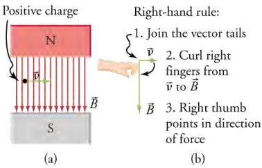
An electron moves through a uniform magnetic field. (b) Using the right-hand rule, the force on the electron is found to be
directed into the page.
Electric Motors, Generators, and Transformers
As we learned previously, a current-carrying wire in a magnetic field experiences a force-recall F = IlB sin θ. Electric motors, which convert electrical energy into mechanical energy, are the most common application of magnetic force on current carrying wires. Motors consist of loops of wire in a magnetic field. When current is passed through the loops, the magnetic field exerts a torque on the loops, which rotates a shaft. Electrical energy is converted to mechanical work in the process. The diagram below shows a schematic drawing of an electric motor.
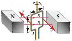
Torque on a current loop. A vertical loop of wire in a horizontal magnetic field is attached to a vertical shaft. When current is
passed through the wire loop, torque is exerted on it, making it turn the shaft.
Let us examine the force on each segment of the loop in the diagrm shown above to find the torques produced about the axis of the vertical shaft - this will lead to a useful equation for the torque on the loop. We take the magnetic field to be uniform over the rectangular loop, which has width w and height las shown in the figure. First, consider the force on the top segment of the loop. To determine the direction of the force, we use the right-hand rule. The current goes from left to right into the page, and the magnetic field goes from left to right in the plane of the page. Curl your right fingers from the current vector to the magnetic field vector and your right thumb points down. Thus, the force on the top segment is downward, which produces no torque on the shaft. Repeating this analysis for the bottom segment-neglect the small gap where the lead wires go out—shows that the force on the bottom segment is upward, again producing no torque on the shaft.
Consider now the left vertical segment of the loop. Again using the right-hand rule, we find that the force exerted on this segment is perpendicular to the magnetic field, as shown above. This force produces a torque on the shaft. Repeating this analysis on the right vertical segment of the loop shows that the force on this segment is in the direction opposite that of the force on the left segment, thereby producing an equal torque on the shaft. The total torque on the shaft is thus twice the toque on one of the vertical segments of the loop.
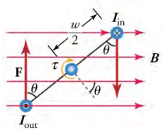
View from above of the wire loop from in the torque on a current loop image. The magnetic field generates a force F
on each vertical segment of the wire loop, which generates a torque on the shaft. Notice that the currents Iin and
Iout have the same magnitude because they both represent the current flowing in the wire loop, but Iin
flows into the page and Iout flows out of the page.
To find the magnitude of the torque as the wire loop spins, consider the diagram above, which shows a view of the wire loop from above. Recall that torque is defined as t = rF sin θ where F is the applied force, r is the distance from the pivot to where the force is applied, and θ is the angle between r and F. Notice that, as the loop spins, the current in the vertical loop segments is always perpendicular to the magnetic field. Thus, the equation F = IlB sin θ gives the magnitude of the force on each vertical segment as F = IlB. The distance r from the shaft to where this force is applied is w/2, so the torque created by this force is
tsegment = rF sin θ = w/2IlB sin θ = (w/2)IlB sin θ [20.10]
Because there are two vertical segments, the total torque is twice this, or
t = wIlB sin θ [20.11]
If we have a multiple loop with N turns, we get N times the torque of a single loop. Using the fact that the area of the loop is A = wl the expression for the torque becomes
t = NIAB sin θ [20.12]
This is the torque on a current-carrying loop in a uniform magnetic field. This equation can be shown to be valid for a loop of any shape.
From the equation t = NIAB sin θ, we see that the torque is zero when θ = 0. As the wire loop rotates, the torque increases to a maximum positive torque of wlB when θ, = 90o. The torque then decreases back to zero as the wire loop rotates to θ, = 180o. From θ = 180o to θ = 360o, the torque is negative. Thus, the torque changes sign every half turn, so the wire loop will oscillate back and forth.
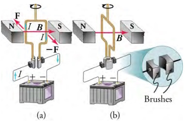
For the coil to continue rotating in the same direction, the current is reversed as the coil passes through using automatic switches called brushes, as shown below.
Consider now what happens if we run the motor in reverse; that is, we attach a handle to the shaft and mechanically force the coil to rotate within the magnetic field, as shown below.26. As per the equation F = qvB sin θ - where is the angle between the vectors and - charges in the wires of the loop experience a magnetic force because they are moving in a magnetic field. Again using the right-hand rule, where we curl our fingers from vector to vector ,we find that charges in the top and bottom segments feel a force perpendicular to the wire, which does not cause a current. However, charges in the vertical wires experience forces parallel to the wire, causing a current to flow through the wire and through an external circuit if one is connected. A device such as this that converts mechanical energy into electrical energy is called a generator.
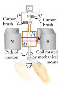
When this coil is rotated through one-fourth of a revolution, the magnetic flux changes from its maximum to zero, inducing
an emf, which drives a current through an external circuit.
Because current is induced only in the side wires, we can find the induced emf by only considering these wires. Motional emf in a straight wire moving at velocity v through a magnetic field B is E = Blv where the velocity is perpendicular to the magnetic field. In the generator, the velocity makes an angle θ with B (see the diagram below), so the velocity component perpendicular to B is θ. Thus, in this case, the emf induced on each vertical wire segment is E = Blv sin θ, and they are in the same direction. The total emf around the loop is then
E = 2Blv sin θ
Although this expression is valid, it does not give the emf as a function of time. To find how the emf evolves in time, we assume that the coil is rotated at a constant angular velocity ω. The angle θ is related to the angular velocity by θ = ωt, so that
E = 2Blv sin ωt
Recall that tangential velocity v is related to angular velocity ω by v = rω. Here, r = w/2, so that v = (w/2)ω and
E = 2Bl(w/2)ωt = Blwωsinωt
Noting that the area of the loop is A = l and allowing for N wire loops, we find that
E = NABω sin ωt
is the emf induced in a generator coil of N turns and area A rotating at a constant angular velocity ω in a uniform magnetic field B. This can also be expressed as
E = E0 sin ωt
where
E0 =NABω
is the maximum (peak) emf
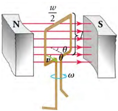
The instantaneous velocity of the vertical wire segments makes an angle with the magnetic field. The velocity is shown in
the figure by the green arrow, and the angle θ is indicated.
The diagram below shows a generator connected to a light bulb and a graph of the emf vs. time. Note that the emf oscillates from a positive maximum of E0 to a negative maximum of -E0 In between, the emf goes through zero, which means that zero current flows through the light bulb at these times. Thus, the light bulb actually flickers on and off at a frequency of 2f, because there are two zero crossings per period. Since alternating current such as this is used in homes around the world, why do we not notice the lights flickering on and off? In the United States, the frequency of alternating current is 60 Hz, so the lights flicker on and off at a frequency of 120 Hz. This is faster than the refresh rate of the human eye, so you don't notice the flicker of the lights. Also, other factors prevent various different types of light bulbs from switching on and off so fast, so the light output is smoothed out a bit.
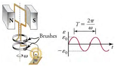
The emf of a generator is sent to a light bulb with the system of rings and brushes shown. The graph gives the emf of the
generator as a function of time. E0 is the peak emf. The period is T = 1/f = 2Π/ω where f is the
frequency at which the coil is rotated in the magnetic field.
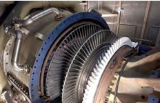
Steam turbine generator. The steam produced by burning coal impacts the turbine blades, turning the shaft which is
connected to the generator. (credit: Nabonaco, Wikimedia Commons)
Another very useful and common device that exploits magnetic induction is called a transformer. Transformers do what their name implies - they transform voltages from one value to another; the term voltage is used rather than emf because transformers have internal resistance. For example, many cell phones, laptops, video games, power tools, and small appliances have a transformer built into their plug-in unit that changes 120 V or 240 V AC into whatever voltage the device uses. The picture below shows two different transformers. Notice the wire coils that are visible in each device. The purpose of these coils is explained below.
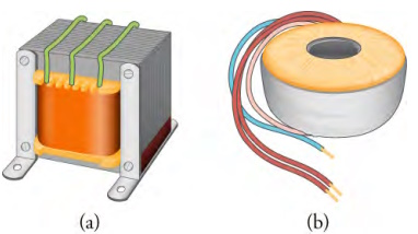
On the left is a common laminated-core transformer, which is widely used in electric power transmission and electrical
appliances. On the right is a toroidal transformer, which is smaller than the laminated-core transformer for the same power
rating but is more expensive to make because of the equipment required to wind the wires in the doughnut shape.
Shown below is a laminated-coil transformer, which is based on Faraday's law of induction and is very similar in construction to the apparatus Faraday used to demonstrate that magnetic fields can generate electric currents. The two wire coils are called the primary and secondary coils. In normal use, the input voltage is applied across the primary coil, and the secondary produces the transformed output voltage. Not only does the iron core trap the magnetic field created by the primary coil, but also its magnetization increases the field strength, which is analogous to how a dielectric increases the electric field strength in a capacitor. Since the input voltage is AC, a time-varying magnetic flux is sent through the secondary coil, inducing an AC output voltage.
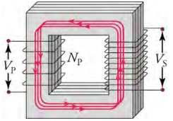
A typical construction of a simple transformer has two coils wound on a ferromagnetic core. The magnetic field created by the
primary coil is mostly confined to and increased by the core, which transmits it to the secondary coil. Any change in current
in the primary coil induces a current in the secondary coil.
Article source: OpenStax is a nonprofit educational technology initiative based at Rice University. OpenStax's mission is to improve educational access and learning for everyone. Textbooks on OpenStax's site are licensed under a Creative Commons Attribution 4.0 International License.

