
Electric forces are described using the concept of the electric field, which is a force field around electric charges that describes the force on any other charge placed in the field. Likewise, a magnet creates a magnetic field around it that describes the force exerted on other magnets placed in the field. As with electric fields, the pictorial representation of magnetic field lines is very useful for visualizing the strength and direction of the magnetic field.

The black lines represent the magnetic field lines of a bar magnet. The field lines point in the direction that the north pole of a
small compass would point, as shown at left. Magnetic field lines never stop, so the field lines actually penetrate the magnet to form
complete loops, as shown at right.
As shown above, the direction of magnetic field lines is defined to be the direction in which the north pole of a compass needle points. If you place a compass near the north pole of a magnet, the north pole of the compass needle will be repelled and point away from the magnet. Thus, the magnetic field lines point away from the north pole of a magnet and toward its south pole.

Magnetic field lines can be drawn by moving a small compass from point to point around a magnet. At each point, draw a
short line in the direction of the compass needle. Joining the points together reveals the path of the magnetic field lines. Another way to
visualize magnetic field lines is to sprinkle iron filings around a magnet, as shown at right.

When two north poles are approached together, the magnetic field lines repel each other and the two magnets experience
a repulsive force. The same occurs if two south poles are approached together. (b) If opposite poles are approached together, the magnetic
field lines become denser between the poles and the magnets experience an attractive force.
The magnetic field is stronger where the lines are denser. Thus, between the two north poles, the magnetic field is very weak because the density of the magnetic field is almost zero. A compass placed at that point would essentially spin freely if we ignore Earth’s magnetic field. Conversely, the magnetic field lines between the north and south poles are very dense, indicating that the magnetic field is very strong in this region. A compass placed here would quickly align with the magnetic field and point toward the south pole on the right.

Instrument for magnetic resonance imaging (MRI). The device uses a cylindrical-coil electromagnet to produce for the main
magnetic field. The patient goes into the tunnel on the gurney.
Note that magnets are not the only things that make magnetic fields. Early in the nineteenth century, people discovered that electrical currents cause magnetic effects. The first significant observation was by the Danish scientist Hans Christian Oersted (1777–1851), who found that a compass needle was deflected by a current-carrying wire. This was the first significant evidence that the movement of electric charges had any connection with magnets. An electromagnet is a device that uses electric current to make a magnetic field. These temporarily induced magnets are called electromagnets. Electromagnets are employed for everything from a wrecking yard crane that lifts scrapped cars to controlling the beam of a 90-km-circumference particle accelerator to the magnets in medical-imaging machines.
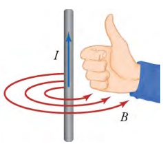
This image shows how to use the right-hand rule to determine the direction of the magnetic field created by current flowing
through a straight wire. Point your right thumb in the direction of the current, and the magnetic field will be in the direction
in which your fingers curl.
The magnetic field created by an electric current in a long straight wire is shown above. The magnetic field lines form concentric circles around the wire. The direction of the magnetic field can be determined using the right-hand rule. This rule shows up in several places in the study of electricity and magnetism. Applied to a straight current-carrying wire, the right-hand rule says that, with your right thumb pointed in the direction of the current, the magnetic field will be in the direction in which your right fingers curl, as shown in Figure 20.13. If the wire is very long compared to the distance r from the wire, the strength B of the magnetic field is given by
Bstraightwire = (u0I)/(2πr)
where I is the current in the wire in amperes. The SI unit for magnetic field is the tesla (T). The symbol - read "mu-zero" - is a constant called the "permeability of free space" and is given by
u0 = 4π x 10-7Txm/A
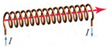
A wire coil with current running through as shown produces a magnetic field in the direction of the red arrow.
Each loop of wire contributes to the magnetic field inside the solenoid. Because the magnetic field lines must form closed loops, the field lines close the loop outside the solenoid. The magnetic field lines are much denser inside the solenoid than outside the solenoid. The resulting magnetic field looks very much like that of a bar magnet, as shown below. The magnetic field strength deep inside a solenoid is
Bsolenoid = u0 (NI)/l
where N is the number of wire loops in the solenoid and l is the length of the solenoid.
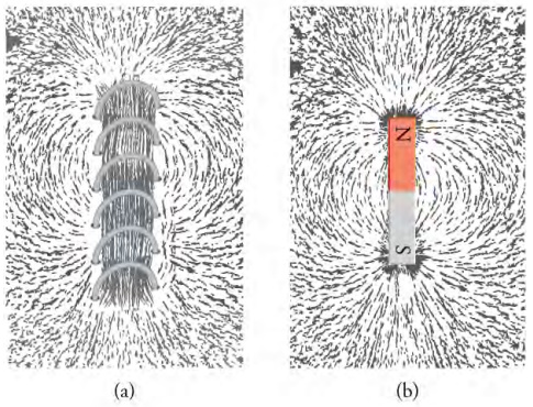
Iron filings show the magnetic field pattern around (a) a solenoid and (b) a bar magnet. The fields patterns are very similar,
especially near the ends of the solenoid and bar magnet.
Article source: OpenStax is a nonprofit educational technology initiative based at Rice University. OpenStax's mission is to improve educational access and learning for everyone. Textbooks on OpenStax's site are licensed under a Creative Commons Attribution 4.0 International License.
