
![]()
Digi-key Part Number 237-1911-ND 115V 6.3V 680mA Power Transformer
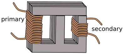
A Transformer consist of a ferromagnetic core around which two wire coils, one referred to as the primary winding, and the other referred to as the secondary winding, are wound. When AC current is applied to the primary winding the coil creates a pulsing magnetic field.
The changing magnetic flux in the iron core causes the magnetic field to reach the secondary coil. Once the magnetic field reaches the secondary coil, where it forces the electrons within it to move, creating an electric current.
It was found that when using a solid core, currents, called eddy currents, were generated in the core causing energy loss in the form of heat. To reduce these losses, cores are now made of laminated sheets of ferromagnetic material.
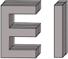
Many transformers are constructed with an E core. AS shown above, the E core is shaped like a capital E. After the windings have been wound on the E core, a bar is placed on the open end of the E.
A transformer's function is to step-up or step-down the voltage from the primary to the secondary windings. This is done by setting the ratio of coil windings on one side relative to the other. If a transformer has 100 windings on the primary and 50 windings on the secondary, it will have a 2:1 winding ratio. It will be a 2:1 step-down transformer, cutting the voltage in half.
If a transformer has 50 windings on the primary and 200 windings on the secondary, it will have a 1:4 winding ratio. It will be a 1:4 step-up transformer, the voltage quadruples from the primary to the secondary.
Though a transformer may step voltage up or down, ignoring losses, power stays the same, so it will provide more current, in inverse to the turns ratio, in the secondary. Similarly a transformer that steps up voltage will provide less current in the secondary.
As you know, impedance is the opposition to alternating current caused by the combined effect of resistance and reactance, measured in ohms. But with transformers, impedance is generally expressed as a percentage. This is because with the large transformers used in the power grid, electricians find ohms not too useful.
Transformer percentage impedance is measured by placing the rated AC voltage on the transformers primary with the secondary shorted out (actually a one ohm power resistor is placed across the secondary). The secondary current is calculated as the inverse of the turns ratio. However due to internal the transformers losses the actual secondary current will be lower. The impedance is the difference in the actual current to the calculated current expressed as a percentage.

More Science, Technology, Engineering, and Mathematics Information:
• Newton's Third Law
• How to Prepare Microscope Slides
• Properties of Algebra
• Brief Description of the Chemical and Physical Properties of Elements in the Periodic Table
• The Diode
• Vectors and Scalars
• Operational Amplifier
• How to Read a Capacitor's Values
• Force Vectors
• Angle Measurement