How to Make a Network Cable
 The steps below are general Ethernet Category 5 (commonly known as Cat 5) cable
construction guidelines. For our example, we will be making a Category 5e patch cable,
but the same general method will work for making any category of network cables.
1. Unroll the required length of network cable and add a little extra, just in case. If a
boot is to be fitted, do so before stripping away the sleeve and ensure the boot faces the correct way.
 2. Carefully remove the outer jacket of the cable, exposing about 1 1/4" (30 mm) of the
twisted pairs. Be careful when stripping the jacket as to not nick or cut the internal
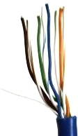
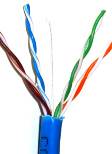
wiring. After removing the outer case, you will notice 8 wires twisted in 4 pairs. Each
pair will have one wire of a certain color and another wire that is white with a colored
stripe matching its partner (this wire is called a tracer). Sometimes a rip cord (white
thread) is also present.
 3. Inspect the newly revealed wires for any cuts or scrapes that expose the copper wire
inside. If you have breached the protective sheath of any wire, you will need to cut the
entire segment of wires off and start over at step one. Exposed copper wire will lead to
cross-talk, poor performance or no connectivity at all. It is important that the jacket
for all network cables remains intact.
 4. Untwist the pairs so they will lay flat between your fingers. The white piece of thread
can be cut off even with the jacket and disposed (see Warnings). For easier handling, cut
the wires so that they are 3/4" (19 mm) long from the base of the jacket.
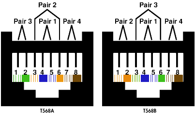
 5. Arrange the wires based on the wiring specifications you are following. There are two
methods set by the TIA, 568A and 568B. Which one you use will depend on what is being
connected. A straight-through cable is used to connect two different-layer devices (e.g. a
hub and a PC). Two like devices normally require a cross-over cable. The difference
between the two is that a straight-through cable has both ends wired identically, while a
cross-over cable has one end wired 568A and the other end wired 568B. For our demonstration
in the following steps, we will use 568B, but the instructions can easily be adapted to 568A.
• 568B - Put the wires in the following order, from left to right:
- white orange
- orange
- white green
- blue
- white blue
- green
- white brown
- brown
• 568A - from left to right: white/green, green, white/orange, blue, white/blue,
orange, white/brown, brown. You can also use the mnemonic 1-2-3-6/3-6-1-2 to remember which
wires are switched.

| 
