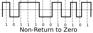
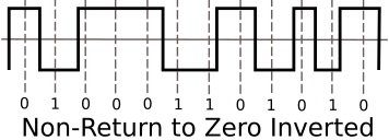
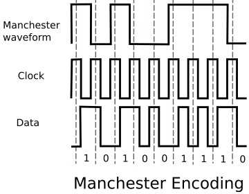
NRZ (Non-Return-to-Zero), NRZI (Non-Return-to-Zero Inverted), and Manchester Encoding are terms for the shapes and voltage levels of digital electronic signals.

Diagram shows voltage on vertical axis,time on
horizontal axis, like an oscilloscope screen.
First lets describe a "usual" digital electronic signal. With a usual digital signal, the binary bit 0 is represented by one voltage level (usually 0 volts), and binary bit 1 is represented by a different voltage level. In the early days that would be 5 volts, but with modern computer circuit boards that may be 2.5 volts. In other words, a binary 0 is represented by a low voltage, and a binary 1 is represented by a high voltage.

Lets call this usual signal RZ for Return to Zero. This signal is fine across a circuit board, but when you send it over a cable, real-world properties like resistance, capacitance, and inductance, make it difficult to return the signal to zero. It then becomes difficult to detect a bit 0 logic level. To reliably detect a bit 0 logic level, we have to pull the signal below 0 volts.
An NRZ signal represents a binary 0 with a negative voltage, and a binary 1 with a positive voltage. For example Ethernet over twisted pair uses -2.5 and +2.5 volts.

At some point the signal needs to be converted to RZ to interface with the components on a computer circuit board. The electronic circuit required to do that is made slightly simpler if you represent binary 0 with the a positive voltage, and a binary 1 with the negative voltage. That's why NRZI, Non-return-to-zero inverted was invented.
To convert a signal to RZ you need to sample the signal, that is measure its voltage, at precise time intervals. This is accomplished using a clock signal. The data signal voltage is sampled on either the rising edge or falling edge of the clock signal. So you need more than one conductor to send the data, you need a conductor for the clock signal.
However, with a Manchester encoded signal, the clock signal is combined with the data signal. With Manchester Encoding, a binary 1 is represented by a low to high transition [01], and a binary 0 is represented by a high to low transition [10]. Another form of Manchester Encoding, called Differential Manchester Encoding, adds a transition at the midpoint of the pulse period to increase the number of voltage transitions for easier extraction of the clock signal.
In this article, I'm not going into detail on how to perform Manchester Encoding because information about that is all over the Internet. But information about how to extract the binary data from a Manchester encoded signal is extremely scarce, therefore I'll explain that instead.

A phase-locked loop (PLL) is an electronic circuit that oscillates at a specific frequency. The special thing about a PLL is that it takes an input signal, such as a Manchester signal, and the voltage transitions of the input signal will cause the output oscillation of the PLL to sync up with the input signal. That is how the clock signal is extracted from the Manchester signal.
Note in the diagram that the Manchester signal is sampled in the center of each clock pulse. This accomplished by using a frequency multiplying circuit to create a falling edge in the center of each clock pulse. The logic level of the Manchester signal is then XORed with the logic level of the clock signal to recreate the original data signal.
Of course this is not the only way the data signal is extracted from the Manchester signal. There are many creative, and patented methods of extracting the data signal is from the Manchester signal. That's because Manchester encoding is the digital transmission method used by Ethernet.
More Networking Basics:
• Network Patch Panel Basics
• What is DSL and how can it benefit my home or small business?
• Bluetooth in Brief
• Synchronous, Asynchronous, Isochronous. What Does it Mean?
• Satellite Broadband Internet Service
• Basics of Bluetooth Technology
• Bluetooth Basics - Bluetooth Technology Tutorial
• Network Classifications: LAN, WAN, WLAN, SAN, MAN, and PAN
• Home and Small Office Networking Guide
• What is DNS?

