Computer Networking Topologies
By Stephen Bucaro
The physical arrangement of the cables, computers and components is referred to as the
networks topology. There are five basic topologies, bus, star, ring, mesh, and wireless.
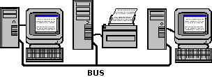
Bus Topology
A bus topology consists of a cable that connects all the computers in the network in
a single line. Computers communicate by attaching the address of the computer meant
to receive it to the data and putting it on the cable. The data, an electronic signal,
travels to the ends of the cable. A component called a terminator is connected to
each end of the cable to absorb the signal and prevent it from bouncing back.

If the cable is disconnected or physically broken, this would result in cable ends that
do not have a terminator. Signals would bounce, causing the network communications to fail.
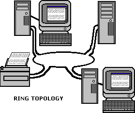
Ring Topology

In a ring topology, all the computers in the network are connected in a closed loop.
The data signal travels around the loop in one direction, passing through each computer.
Whereas bus topology is passive, in a ring topology each computer boosts the signal
before sending it on to the next computer. Because the signal must pass through each
computer, the failure of one computer can cause the network to fail.
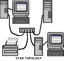
Star Topology

In a star topology, all the computers in the network are connected by cable
to a central hub. This configuration results in better fault tolerance because a
problem with one cable will not affect the rest of the network. However, if the
central hub fails, it brings down the entire network. Star topology may require more
cable than bus or ring topology.
Mesh Topology
In a mesh topology, each computer in the network is directly connected to every other
computer in the network. Mesh topology has very high fault tolerance because if one
cable breaks, several alternate routes are available. Mesh topology is very complex
and requires a large amount of cable. It is not cost effective to implement except
for the most mission critical systems.
Wireless Topology
A wireless network dosn't use cables. Instead a wireless network uses infrared light
beams or radio waves to communicate. The wireless network consists of transceivers
called access points. The computers in a wireless network each have their own transceivers
to communicate with an access point. In an infrared light network, the client and the
access point must be in line-of-sight.
Logical vs. Physical Topology
The logical topology is the way the data is transferred between devices on
a network, as apposed to the physical topology which is the actual physical
layout of the network cabling. The logical topology of a network is not necessarily
the same as its physical topology. For example, Ethernet networks use the bus
logical topology, but commonly use the star logical topology.
Understanding the difference between the logical and physical topology of a network
is important in troubleshooting. For example, in an Ethernet network, although each
network device physically connects to a hub, its logical topology means that a single
malfunctioning device can transmit bad packets to all other devices on the same subnet.
More Networking Topologies Articles:
• Technologies for the Internet of Things (IoT)
• What is Fiber Optic Splicing?
• What Are Fiber Optic Attenuators?
• An introduction to Linux Network Routing
• Network Topologies
• Trunking, Bonding, Aggregation; What Does it Mean?
• Understanding the Basics of All-Optical Switching
• System Area Network Interface Cards
• Bluetooth Basics
• Wireless Networking Infrastructure Mode
| 
