

Modern institutional LANs are often configured hierarchically, with each workgroup (department) having its own switched LAN connected to the switched LANs of other groups via a switch hierarchy. While such a configuration works well in an ideal world, the real world is often far from ideal. Three drawbacks can be identified in the configuration in Figure 6.15:
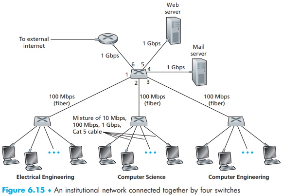
• Lack of traffic isolation. Although the hierarchy localizes group traffic to within a single switch, broadcast traffic (e.g., frames carrying ARP and DHCP messages or frames whose destination has not yet been learned by a self-learning switch) must still traverse the entire institutional network. Limiting the scope of such broadcast traffic would improve LAN performance. Perhaps more importantly, it also may be desirable to limit LAN broadcast traffic for security / privacy reasons. For example, if one group contains the company's executive management team and another group contains disgruntled employees running Wireshark packet sniffers, the network manager may well prefer that the executives' traffic never even reaches employee hosts. This type of isolation could be provided by replacing the center switch in Figure 6.15 with a router. We'll see shortly that this isolation also can be achieved via a switched (layer 2) solution.
• Inefficient use of switches. If instead of three groups, the institution had 10 groups, then 10 first-level switches would be required. If each group were small, say less than 10 people, then a single 96-port switch would likely be large enough to accommodate everyone, but this single switch would not provide traffic isolation.
• Managing users. If an employee moves between groups, the physical cabling must be changed to connect the employee to a different switch in Figure 6.15. Employees belonging to two groups make the problem even harder.
Fortunately, each of these difficulties can be handled by a switch that supports virtual local area networks (VLANs). As the name suggests, a switch that supports VLANs allows multiple virtual local area networks to be defined over a single physical local area network infrastructure. Hosts within a VLAN communicate with each other as if they (and no other hosts) were connected to the switch. In a port-based VLAN, the switch's ports (interfaces) are divided into groups by the network manager. Each group constitutes a VLAN, with the ports in each VLAN forming a broadcast domain (i.e., broadcast traffic from one port can only reach other ports in the group).
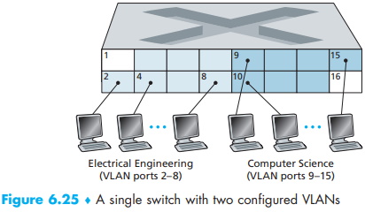
Figure 6.25 shows a single switch with 16 ports. Ports 2 to 8 belong to the EE VLAN, while ports 9 to 15 belong to the CS VLAN (ports 1 and 16 are unassigned). This VLAN solves all of the difficulties noted above - EE and CS VLAN frames are isolated from each other, the two switches in Figure 6.15 have been replaced by a single switch, and if the user at switch port 8 joins the CS Department, the network operator simply reconfigures the VLAN software so that port 8 is now associated with the CS VLAN. One can easily imagine how the VLAN switch is configured and operates - the network manager declares a port to belong to a given VLAN (with undeclared ports belonging to a default VLAN) using switch management software, a table of port-to-VLAN mappings is maintained within the switch; and switch hardware only delivers frames between ports belonging to the same VLAN.
But by completely isolating the two VLANs, we have introduced a new difficulty! How can traffic from the EE Department be sent to the CS Department? One way to handle this would be to connect a VLAN switch port (e.g., port 1 in Figure 6.25) to an external router and configure that port to belong both the EE and CS VLANs. In this case, even though the EE and CS departments share the same physi#cal switch, the logical configuration would look as if the EE and CS departments had separate switches connected via a router. An IP datagram going from the EE to the CS department would first cross the EE VLAN to reach the router and then be forwarded by the router back over the CS VLAN to the CS host. Fortunately, switch vendors make such configurations easy for the network manager by building a single device that contains both a VLAN switch and a router, so a separate external router is not needed.
Returning again to Figure 6.15, let's now suppose that rather than having a separate Computer Engineering department, some EE and CS faculty are housed in a separate building, where (of course!) they need network access, and (of course!) they'd like to be part of their department's VLAN. Figure 6.26 shows a second 8-port switch, where the switch ports have been defined as belonging to the EE or the CS VLAN, as needed. But how should these two switches be interconnected? One easy solution would be to define a port belonging to the CS VLAN on each switch (similarly for the EE VLAN) and to connect these ports to each other, as shown in Figure 6.26(a). This solution doesn't scale, however, since N VLANS would require N ports on each switch simply to interconnect the two switches.
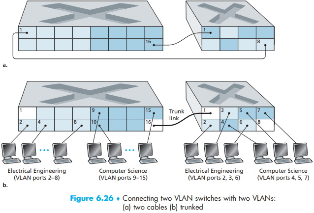
A more scalable approach to interconnecting VLAN switches is known as VLAN trunking. In the VLAN trunking approach shown in Figure 6.26(b), a special port on each switch (port 16 on the left switch and port 1 on the right switch) is configured as a trunk port to interconnect the two VLAN switches. The trunk port belongs to all VLANs, and frames sent to any VLAN are forwarded over the trunk link to the other switch. But this raises yet another question: How does a switch know that a frame arriving on a trunk port belongs to a particular VLAN?
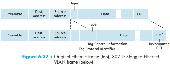
The IEEE has defined an extended Ethernet frame format, 802.1Q, for frames crossing a VLAN trunk. As shown in Figure 6.27, the 802.1Q frame consists of the standard Ethernet frame with a four-byte VLAN tag added into the header that carries the identity of the VLAN to which the frame belongs. The VLAN tag is added into a frame by the switch at the sending side of a VLAN trunk, parsed, and removed by the switch at the receiving side of the trunk. The VLAN tag itself consists of a 2-byte Tag Protocol Identifier (TPID) field (with a fixed hexadecimal value of 81-00), a 2-byte Tag Control Information field that contains a 12-bit VLAN identifier field, and a 3-bit priority field that is similar in intent to the IP datagram TOS field.
In this discussion, we've only briefly touched on VLANs and have focused on port based VLANs. We should also mention that VLANs can be defined in several other ways. In MAC-based VLANs, the network manager specifies the set of MAC addresses that belong to each VLAN; whenever a device attaches to a port, the port is connected into the appropriate VLAN based on the MAC address of the device. VLANs can also be defined based on network-layer protocols (e.g., IPv4, IPv6, or Appletalk) and other criteria. It is also possible for VLANs to be extended across IP routers, allowing islands of LANs to be connected together to form a single VLAN that could span the globe [Yu 2011]. See the 802.1Q standard [IEEE 802.1q 2005] for more details.
About the Authors
Jim Kurose is a Distinguished University Professor of Computer Science at the University of Massachusetts, Amherst. He is currently on leave from the University of Massachusetts, serving as an Assistant Director at the US National Science Foundation, where he leads the Directorate of Computer and Information Science and Engineering.
Dr. Kurose has received a number of recognitions for his educational activities including Outstanding Teacher Awards from the National Technological University (eight times), the University of Massachusetts, and the Northeast Association of Graduate Schools. He received the IEEE Taylor Booth Education Medal and was recognized for his leadership of Massachusetts' Commonwealth Information Technology Initiative. He has won several conference best paper awards and received the IEEE Infocom Achievement Award and the ACM Sigcomm Test of Time Award.
Dr. Kurose is a former Editor-in-Chief of IEEE Transactions on Communications and of IEEE/ACM Transactions on Networking. He has served as Technical Program co-Chair for IEEE Infocom, ACM SIGCOMM, ACM Internet Measurement Conference, and ACM SIGMETRICS. He is a Fellow of the IEEE and the ACM. His research interests include network protocols and architecture, network measurement, multimedia communication, and modeling and performance evaluation. He holds a PhD in Computer Science from Columbia University.
Keith Ross is the Dean of Engineering and Computer Science at NYU Shanghai and the Leonard J. Shustek Chair Professor in the Computer Science and Engineering Department at NYU. Previously he was at University of Pennsylvania (13 years), Eurecom Institute (5 years) and Polytechnic University (10 years). He received a B.S.E.E from Tufts University, a M.S.E.E. from Columbia University, and a Ph.D. in Computer and Control Engineering from The University of Michigan. Keith Ross is also the co-founder and original CEO of Wimba, which develops online multimedia applications for e-learning and was acquired by Blackboard in 2010.
Professor Ross's research interests are in privacy, social networks, peer-to-peer networking, Internet measurement, content distribution networks, and stochastic modeling. He is an ACM Fellow, an IEEE Fellow, recipient of the Infocom 2009 Best Paper Award, and recipient of 2011 and 2008 Best Paper Awards for Multimedia Communications (awarded by IEEE Communications Society). He has served on numerous journal editorial boards and conference program committees, including IEEE/ACM Transactions on Networking, ACM SIGCOMM, ACM CoNext, and ACM Internet Measurement Conference. He also has served as an advisor to the Federal Trade Commission on P2P file sharing.

Unique among computernetworking texts, the 8th Edition, Global Edition, of the popular Computer Networking: A Top Down Approach build son the authors' long tradition of teaching this complex subject through alayered approach in a "top-down manner." The text works its way from the application layer down toward the physical layer, motivating students by exposing them to important concepts early in their study of networking. Focusing on the Internet and the fundamentally important issues of networking, this text provides an excellent foundation for students in computer science and electrical engineering, without requiring extensive knowledge of programming ormathematics. The 8th Edition, Global Edition, has been updated to reflect the most important and exciting recent advances in networking, including the importance of software-defined networking (SDN) and the rapidadoption of 4G/5G networks and the mobile applications they enable.

More Networking Protocols and Standards:
• TCP/IP Features
• Network Operating Systems
• What's the Difference Between a Packet and a Frame?
• Video - Data Link Layer of OSI Networking Model
• What Are Private IP Addresses?
• What is PPP, PPPoA and PPPoE?
• The OSI Presentation Layer
• A Simple Description of the IPv6 Header and Datagram
• The OSI Physical Layer
• IPv6 Unicast Addresses