Fiber Optic Bend Radius Standards
By Stephen Bucaro
Fiber optic communication is a method of transmitting data as light pulses through cables
that are constructed of bundles of thin strands of very pure glass. Compared to copper cables,
fiber-optic cables are immune to electromagnetic interference and so can transmit light
signals reliably over long distances.
However, fiber optic cable can be damaged by placing too much tension on the cable or bending
the cable excessively during installation. Excessive bending or too much pulling force can
permanently damage the fiber by causing micro cracks.

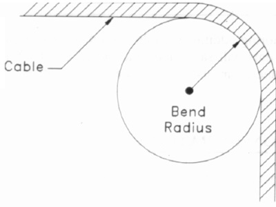
Until recently the minimum bend radius allowable for a given fiber optic cable was set by
the specifications of individual cable manufacturers. The new ANSI/TIA/EIA-568B.3 standard,
"Optical Fiber Cabling Components Standard," sets the minimum bend radius and maximum pulling
tension standards for 50/125-micron and 62.5/125-micron fiber-optic cables.
For inside plant cable standard specifies the minimum bend radius as 10 times the cable's
outside diameter under no pull load (cable being layed in tray) and 15 times the cable's
outside diameter when subject to tensile load. In a cable run you cannot have more than
360 degrees in bends (maximum of four 90 degree bends).
Many cabling pathways available in the industry offer only a 1 inch cable bend radius.
Although a 1 inch bend radius is sufficient for the lay-in of fiber-optic cable, it's not
sufficient for the installation of fiber-optic cable under pull forces. The installation
of cables may be limited by a pathway that does not maintain a minimum 2 inch bend radius.
If a cable run is too long, or if multiple bends are in the conduit, intermediate pull boxes
should be used to separate one long pull into two or more shorter pulls. A cable should not
be pulled through more than two 90 degree bends at one time. If more than two 90 degree
bends are unavoidable, the cable should be installed from a central point, unreeled into
a figure-eight, and then backfed to complete the installation.
Tensile Loading
There are two tension specifications for fiber optic cables. One is the maximum load the
cable can be subjected to without causing permanent damage. The use of a swivel is recommended
when pulling a cable in a tray. The swivel allows the cable and pulling rope to twist independently.
The other is the cable weight when running a cable vertically. If a long vertical run is
necessary, cable should be secured at each floor and service loops should be placed every
three floors to help distribute the weight of the cable vertically.
More Network Troubleshooting and Support Articles:
• How Snort's Stealth TCP Port Scanning Works
• Putting Your SME Data on the Internet
• Turning Names (URLs) Into IP Addresses
• Network Installation
• Five Free Tools Every Network Administrator Should Have
• Network Cabling Do's and Don'ts
• Calculating VoIP Bandwidth
• To Avoid Network Downtime Perform Risk Assessment
• How to Use a Network Cable Toner
• What is the Difference Between NAT and PAT?
| 
