When we say a computer system has a 16-bit bus, what we mean is that it can transfer binary data around internally in chunks of 16 binary bits simultainiously. To transfer 16 binary bits simultainiously requires 16 separate wires or metal traces on a printed circuit board. Along with the 16 binary bits of data, we'll need a few more wires or traces for the control signals particular to that bus. The whole group of wires or traces is referred to as a "bus".
You can think of it as a bus that all the people related to the bus board to be transferred from the source to the destination. Actually a bus is more like a super-highway. A 16-bit bus would be a super-highway with 16 lanes, each binary bit using a separate lane (changing lanes is strictly forbidden). A 16-bit bus would actually be a super-highway with more than 16 lanes because you need those control signals.
The super-highway metaphor is more accurate because a computer bus is usually connected to several or many electronic devices. It would be like a super-highway with many on-ramps and off-ramps. The binary bits actually arrive at all on-ramps and off-ramps simultainiously, it's the control signals that determine which devices send or receive any specific chunk of binary data.
A computer has many different types of buses. The primary buses are the address bus and the data bus. The address bus identifies where the data is to come from or the data's destination. An address bus may be 64-bits wide. But there may also be specific buses for storage devices and input/output devices. And then there are different versions of each type, with a different number of bits (bus width) and a different transfer speed for each type. Let's explore some of the main types of buses.
Industry Standard Architecture (ISA) Bus
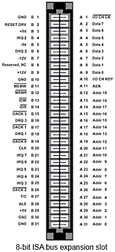
Image from Wikimedia Commons
The ISA bus was one of the first bus standards, and it was introduced with the first IBM PC's. It originated as an 8-bit bus, but was quickly updated to 16-bit for use with Intel's 80286 processor. The 8-bit bus ran at 4.77 MHz, the 16-bit bus ran at 6 or 8 MHz. The 8-bit bus used a 8259 Programmable Interrupt Controller (PIC), giving 8 interrupt lines. It had 4 DMA channels, 3 brought out to the expansion slots, 2 of these were normally allocated to the disk drive and hard disk controller.
The biggest problem with the ISA bus was that to add hardware to the system, you couldn't just plug it in, you were required to understand IRQ, DMA, and I/O address settings, and to manually set appropriate dip switches to configure those resources for the new hardware.
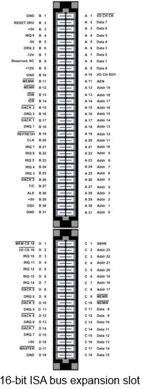
Image from Wikimedia Commons
The original 8-bit ISA bus was expanded to 16-bits by adding a second shorter edge connector in-line with the 8-bit connector. This allowed compatibility with 8-bit expansion cards. The second connector added 4 additional address lines for a total of 24, and 8 additional data lines for a total of 16. It also added a second 8259 PIC providing 7 additional interrupt lines and 4 additional DMA channels, and control lines to select 8 or 16 bit transfers.
Extended Industry Standard Architecture (EISA) Bus
EISA extended the ISA bus to 32 bits and ran at 8.33 MHz. It also provide control lines that allowed bus mastering. The ISA bus allowed only one device (a single CPU) to control the bus. Bus mastering allows more than one device to take control of the bus (but not all at the same time). Bus mastering allows more than one CPU to share the bus. Bus mastering also allowed the EISA bus to support 4 GB of memory. The EISA bus was backward compatible with 8-bit and 16-bit ISA expansion cards.
Peripheral Component Interconnect (PCI) Bus
The PCI bus is 32-bit or 64-bit bus running at 33 MHz. Its address, data, and control lines are in a standard format that's independent of any particular processor. The PCI 1.0 standard used 5 volt signals. The PCI 2.0 standard ran at 66 MHz and used 3.3 volt signals.
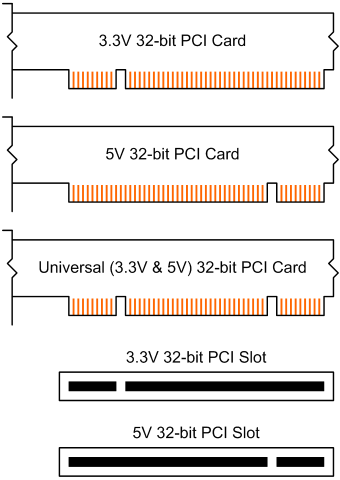
Image from Wikimedia Commons
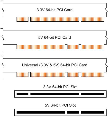
Image from Wikimedia Commons
The type of expansion card allowed to be inserted was controled by the location of a notch in the card. Universal cards, which can operate on both PCI 1.0 and 2.0 have two notches.
Peripheral Component Interconnect Express (PCIe) Bus
The architectures discussed so far are parallel buses. PCIe is a serial bus architecture. You might not think of a serial connection as being a bus, but it does become a bus when you consider the control lines. Each PCIe serial connection is called a "lane". PCIe X1 has one lane. PCIe X2 has two lanes. PCIe X16 has 16 lanes. Each lane is bi-directional and consists of a transmit differential pair of connections, and a receive differential pair of connections, along with control and test connections. PCIe allows hot plugging and hot swapping.
A PCIe version 1 lane had a transfer rate of 250 MB/s (125 MB/s in each direction). A PCIe version 2 lane had a transfer rate of 500 MB/s (250 MB/s in each direction). A PCIe 3.0 lane has a transfer rate of 500 MBps in each direction for a total bandwidth 1 GBps. Lanes can be grouped to increase bandwidth. A device that uses 4 lanes creates an X4 connection having a bandwidth of 4 GB/s.
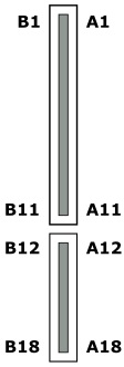
With PCIe expansion cards you can usually determine the number of lanes the card uses by the size of its connector. Shown above is a PCIe X1 connector. Shown below is the pinout of a PCIe X1 connector.
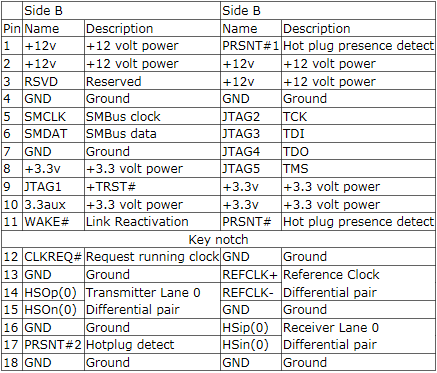
Some of the important connections are the HSO and HSI transmit and receive differential pair, the PRSNT connections used to indicate whether a card has been plugged into the connector, and the JTAG connections which are a test access point (Joint Test Action Group).
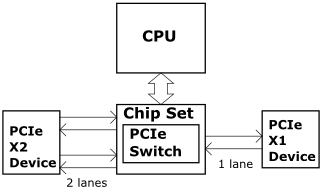
The PCIe bus works more like an onboard network than like a bus.
More Computer Architecture Articles:
• The Computer's Chipset
• CPU Process Scheduling
• How Computer Memory Works
• Digital Logic Levels and Transfer Characteristics
• Direct Memory Access (DMA)
• CPU Chip Packaging
• Inductors in DC Circuits
• Microcontroller Architectures
• Windows Operating System Services, Functions, Routines, Processes, Threads, and Jobs
• Operating System Memory Paging Hardware Support

