

The good thing about CPU registers is that they are part of the CPU, and an operand located in these registers is immediately available as input to the arithmetic and logic unit (ALU). Since the instructions having operands in the registers of the CPU are executed faster, the microcontrollers designed for higher speed tend to have more internal registers. While HC11 has only two accumulator registers, the AVR family has as many as 32 such registers.
The CPU Registers of HC11
HC11 has seven internal registers, plus the CPU status register, called the Condition Code Register (CCR).
The accumulator registers A and B are general-purpose 8-bit registers. They can be concatenated to form a 16-bit register called D, where A is the most significant byte, and B is the least significant byte. This feature creates a remarkable flexibility for 16-bit arithmetic operations.
The index registers X and Y are 16-bit registers, which can also be used as storage registers, 16-bit counters; and most important, they can store a 16-bit value, which, added with an 8-bit value contained in the instruction itself, form the effective address of the operand when using the indexed addressing mode.
The Stack Pointer (SP) register is a 16-bit register, that must be initialized by software with the ending address of a RAM memory area, called the stack. SP automatically decrements each time a byte is pushed to the stack, and increments when a byte is pulled from stack. Thus, SP always points to the first free location of the stack. The stack is affected in the following situations:
• During the execution of the instructions BSR, JSR (Branch or Jump to Subroutine), the return address is automatically pushed on to the stack and the SP is adjusted accordingly. The instruction RTS (Return from Subroutine) pulls this value from the stack and reloads it into the program counter.
• During the execution of push and pull type instructions, used to save and restore the contents of the CPU registers to the stack.
• During the execution of an interrupt, and when returning from an interrupt service routine upon the execution of the RTI (Return from Interrupt) instruction.
SP may be directly accessed by means of the LDS (load SP) and STS (Store SP) instructions or indirectly, using transfer instructions like TXS, TYS (Transfer X/Y to SP) or TSX, TSY (Transfer SP to X/Y).
The Program Counter (PC) register is a 16-bit register, that contains the address of the instruction following the instruction currently executed.
The Condition Code Register (CCR) is an 8-bit register with the following structure:
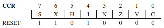
The bits C (Carry/Borrow), V (Overflow), Z (Zero), N (Negative) and H (Half Carry) are status bits, set or cleared according to the result of the arithmetic and logic instructions. Refer to the data sheet for details on how these bits are affected by each instruction.
The bits I (General Interrupt Mask), X (XIRQ Interrupt Mask), and S (Stop disable) are control bits used to enable/disable the interrupts, or the low-power operating mode. When I = 1 all maskable interrupts are disabled. X = 1 disables the non-maskable interrupt XIRQ, and S = 1 blocks the execution on the STOP instruction, which is treated like a NOP.
Some CCR bits (C, V, I) can be directly controlled by means of the instructions SEC (Set Carry), CLC (Clear Carry), SEV (Set Overflow Bit), CLV (Clear Overflow Bit), SEI (Set Interrupt Mask), and CLI (Clear Interrupt Mask). The CCR as a whole may be read or written using the instructions TPA (Transfer CCR to A) and TAP (Transfer A to CCR).
The CPU Registers of AVR
The CPU of the AVR microcontrollers has 32 general-purpose registers, called R0- R31. The register pairs R26-R27, R28-R29, R30-R31 can be concatenated to form the X, Y, Z , registers, which can be used for indirect addressing (R26 is XL - lower byte of X, R27 is XH - higher byte of X, R28 is YL, R29 is YH, R30 is ZL and R31 is ZH). The registers R16-R31 may be the destination of immediate addressed operands like LDI (Load Register Immediate) or CPI (Compare Immediate). Unlike HC11, the CPU registers of AVR are present with distinct addresses in the memory map.
The Program Counter (PC) has functions similar to those of the PC register of HC11. The difference is that the size of PC is not 16 bits, and is limited to the length required to address the program memory (in case of AT90S8515 only 12 bits are needed to address the 4K of program memory). PC is cleared at RESET.
The Stack Pointer (SP) has 16 bits, and is placed in the I/O register address space, which makes it accessible to the programmer only by means of the IN and OUT instructions, as two 8-bit registers SPH, and SPL.
The CPU status register is called SREG and has the following structure:
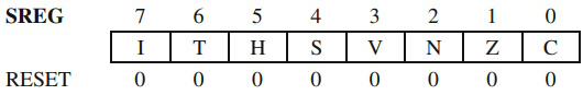
The meaning of the bits in SREG is slightly different from those of HC11:
The I bit - Global Interrupt Enable/Disable Bit - has an opposite action: when set to 1 the interrupts are enabled. The instructions that control this bit have the same mnemonic SEI (Set I bit) and CLI (Clear I bit).
T - Bit Copy Storage. The status of this bit can be modified by the instructions BST (Bit Store) and BLD (Bit Load), thus allowing the program to save the status of a specific bit from a general-purpose register, or transfer this information to a bit from another register. There is also a pair of conditional branch instructions which test this bit: BRTS (Branch if T bit is Set), and BRTC (Branch if T bit is Clear).
S -Sign Bit - It is the exclusive OR between N and V
The other bits in SREG (C, Z, N, V, H) have the same meaning described for HC11. The AVR microcontrollers have distinct SET-CLEAR instructions for each of the SREG bits.
The CPU Registers of 8051
The accumulator A is a general-purpose 8-bit register, used to store operands or results in more than a half of the instruction set of 8051.
The R0-R7 registers are 8-bit registers, similar to the registers R0-R31, described for the AVR family of microcontrollers. There are four sets (or banks) of such registers, selected by writing the bits [RS1:RS0] in the CPU status register PSW, described below.
The four sets of eight registers each occupy 32 addresses in the address space of data memory, at the addresses [0000h-0007h], [0008h-000Fh], [0010h-0017h], [0018h-001Fh] (refer to Fig. 1.4).
The accumulator B is another general-purpose 8-bit register, having functions similar to the R0-R7 registers. Besides that, the accumulator B is used to store one of the operands in the case of the arithmetic instructions MUL AB and DIV AB.
The Data Pointer Register (DPTR) is a 16-bit register, used for indirect addressing of operands, in a similar way to the X, Y, Z registers of AVR.
The Program Counter (PC) is a 16-bit register similar to the PC of HC11. PC is cleared at RESET, thus all programs start at the address 0000h.
The Stack Pointer (SP) has the following distinctive features, compared to HC11 and AVR:
• It is an 8-bit register, i.e. it can address a memory area of 256 bytes maximum.
8051 can only use the internal memory for the stack.
• Unlike HC11 and AVR where SP is initialized with an address at the end of RAM,
and decrements with each byte pushed on to the stack, the SP of 8051 increments when data
is added to the stack.
• For HC11 and AVR, SP points to the first free byte of the stack area. The
SP of 8051 indicates the last occupied location of the stack. At RESET, SP is automatically
initialized with 07h, hence the first byte pushed to the stack will occupy the location with the address 08h.
• The Processor Status Word (PSW) is similar to CCR of HC11 or SREG of AVR, and has the following structure:
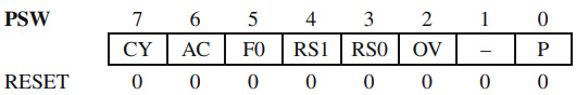
The bits CY, AC and OV have similar functions to the bits C, H, and V of HC11 and AVR.
[RS1:RS0] - Register bank select bits P - Parity bit. P = 1 if the accumulator contains an odd number of 1s, and P = 0 if the accumulator contains an even number of 1s. Thus the number of 1s in the accumulator plus P is always even. The bits PSW1 and PSW5 (F0) are uncommitted and may be used as general-purpose status flags.
About Microcontrollers in Practice

The book is structured into three sections. Chapters 1-8 aim to create a detailed overview of microcontrollers, by presenting their subsystems starting from a general functional block diagram, valid for most microcontrollers on the market. In each case, we describe the distinctive features of that specific subsystem for HC11, 8051 and AVR. This whole section has a more theoretical approach, but, even here, many practical examples are presented, mainly regarding the initializations required by each subsystem, or the particular use of the associated interrupts. The purpose of this section is to create a perspective that views the microcontroller as a set of resources, easy to identify and use.
Chapters 9-16 contain eight complete projects, described from the initial idea, to the printed circuit board and detailed software implementation. Here too, we permanently focus on the similarities between the microcontrollers discussed, from the hardware and software perspectives.
All chapters contain exercises, suggesting modifications or improvements of the examples in the book. Most exercises have solutions in the book; for the others the solutions can be found on the accompanying CD.
Finally, the appendices contain additional information intended to help the reader to fully understand all the aspects of the projects described in the previous sections. We chose to present these details separately in these appendices, in order to avoid fragmentation of the flow of the main text.
Stressing common characteristics and real applications of the most used microcontrollers, this practical guide provides readers with hands-on knowledge of how to implement three families of microcontrollers (HC11, AVR, and 8051). Unlike the rest of the ocean of literature on individual chips, Microcontrollers in Practice supplies side-by-side comparisons and an overview that treats the systems as resources available for implementation. Packed with hundreds of practical examples and exercises to foster mastery of concepts and details, the guide also includes several extended projects. By treating the less expensive 8-bit and RISC microcontrollers, this information-dense manual equips students and home-experimenters with the know-how to put these devices into operation. Click here to learn more.

More Computer Architecture Articles:
• Computer Buses
• Introduction to Microprocessor Programming
• Pi-Top kit - Build Your Own Laptop
• Basic Computer Architecture
• Learn Assembly Language Programming on Raspberry Pi 400
• Operating System Memory Page Sharing
• AMD's Microarchitectures
• Inductors in DC Circuits
• Digital Logic Levels and Transfer Characteristics
• Shortest-Job-First CPU Scheduling Algorithm