

In many cases it is possible that the internal resources of a microcontroller are insufficient for certain applications. A typical example is when the number of variables used to store data exceeds the capacity of the internal RAM memory. The obvious solution to these situations is to add external components by creating an expanded microcontroller structure.
The disadvantage of this solution is that a significant number of the available I/O lines are used to create the external bus for accessing the new resources, and are no longer available for normal I/O operations. Note that not all microcontrollers can operate with an external bus. The following paragraphs describe how to create and use expanded microcontroller structures.
HC11 Operating with External Bus
The HC11 microcontrollers have two pins, called MODA and MODB, which control the operating mode. At RESET the status of these pins is read and, according to the result, the microcontroller selects one of the operating modes listed in Table 1.1.
As shown in Table 1.1, there are four possible operating modes, among which two are special and the other two are normal. In the special bootstrap mode, a small ROM memory area becomes visible in the memory map. This ROM contains a short program, called a bootloader, which is executed after RESET, allowing the user to load and run a program in the internal RAM. This is useful, for example, to program the internal ROM memory. See App. A.5 for details on how to do this.
The special test operating mode is destined for factory testing, and will not be discussed. In the expanded operating mode, some of the MCU I/O lines are used to implement the external bus. In some cases, to reduce the number of I/O lines used for this purpose, the external data bus is multiplexed with the lower byte of the address bus.
Demultiplexing requires an external latch, and a signal AS (Address Strobe), generated by the MCU, as shown in Fig. 1.8.
Besides AS, the MCU generates the signal R/W\ (Read/Write) to specify the direction of the transfer on the data bus.
From the programmer's point of view, when using HC11 in expanded operating mode, the following details must be considered:
• All the MCU resources, except the I/O lines used to implement the external bus,
are still available, and have the same addresses.
• The internal ROM can be disabled by clearing the ROMON bit in the CONFIG register.
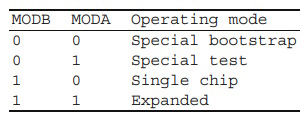
Table 1.1. Selection of the operating mode of HC11
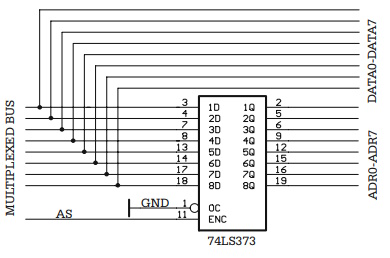
Fig. 1.8. Demultiplexing the external bus
AT90S8515 Operating with External Bus
From the two distinct buses of the AVR microcontrollers, only the bus used for the data memory can be, in some cases, expanded to connect external RAM, or RAM - like external devices. AT90S8515 uses the lines of port A to multiplex the data bus with the lower order address bus, and port C for the high order address bus. The signal that strobes the address into the external latch is called ALE (Address Latch Enable). The direction of the transfer is indicated by two signals RD\ (Read) and WR\ (Write) - both active LOW. The circuit for demultiplexing the bus is identical to the one used by HC11, shown in Fig. 1.8.
The external bus is activated by software, writing 1 to the SRE bit (Static RAM Enable) in the register MCUCR (MCU Control Register). When using slower external memory, there is the possibility of including a WAIT cycle to each access to the external RAM. Writing 1 to the SRW (Static RAM Wait) bit of MCUCR enables this feature.
Some AVR microcontrollers can allocate some of the I/O lines to extend the bus of the data memory for connecting external memory or other RAM-like external devices. Figure A8.1 presents an example of implementation of the external bus for the microcontroller AT90S8515.
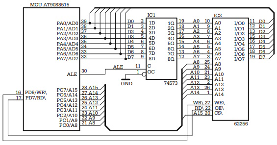
Fig. A8.1. AT90S8515 operating with external bus for data memory
In this example, the external memory is a 32Kx8 62256 circuit, selected directly with the address line A15, which makes it visible in the address range $0000-$7FFF in the address space of the data memory.
The control signals for the external bus are generated by the MCU. ALE (Address Latch Enable) is active HIGH, and strobes the lower half of the address into the external address latch IC1 (74LS573), while RD\ (Read) and WR\ (Write) are active LOW and indicate the direction of the data transfer on the external bus. They are directly connected to the control inputs OE\ and WR\ of the external RAM circuit IC2.
8051 Operating with External Bus
The external bus of 8051 is also multiplexed. Port P0 is used for the data bus and the low-order address bus, and port P2 implements the high-order address bus. The strobe signal for demultiplexing the bus is called ALE (Address latch Enable).
What is specific for 8051 is the capability to access on the same physical bus two pages of external memory: one for program memory, and the other for data memory. The two types of access are distinguished by means of a special signal, called PSEN\ (Program Store Enable), generated by the MCU, active LOW. When PSEN\ is active, the external logic must select an external ROM memory in order to provide program code to the MCU through the data bus. The access to the external RAM is controlled at the hardware level by the signals RD\ (Read) and WR\ (Write), generated by the microcontroller. An additional signal, called EA\ (External Access), active LOW, disables the internal ROM, and redirects all the accesses to the internal program memory (in the address range 0000h-0FFFh) to the external bus. Any access to program memory at addresses higher that 1000h are directed to the external bus regardless of the status of the EA\ input.
At the software level, accessing the external RAM is done by means of the special instruction MOVX (Move to or from external RAM).
About Microcontrollers in Practice

The book is structured into three sections. Chapters 1-8 aim to create a detailed overview of microcontrollers, by presenting their subsystems starting from a general functional block diagram, valid for most microcontrollers on the market. In each case, we describe the distinctive features of that specific subsystem for HC11, 8051 and AVR. This whole section has a more theoretical approach, but, even here, many practical examples are presented, mainly regarding the initializations required by each subsystem, or the particular use of the associated interrupts. The purpose of this section is to create a perspective that views the microcontroller as a set of resources, easy to identify and use.
Chapters 9-16 contain eight complete projects, described from the initial idea, to the printed circuit board and detailed software implementation. Here too, we permanently focus on the similarities between the microcontrollers discussed, from the hardware and software perspectives.
All chapters contain exercises, suggesting modifications or improvements of the examples in the book. Most exercises have solutions in the book; for the others the solutions can be found on the accompanying CD.
Finally, the appendices contain additional information intended to help the reader to fully understand all the aspects of the projects described in the previous sections. We chose to present these details separately in these appendices, in order to avoid fragmentation of the flow of the main text.
Stressing common characteristics and real applications of the most used microcontrollers, this practical guide provides readers with hands-on knowledge of how to implement three families of microcontrollers (HC11, AVR, and 8051). Unlike the rest of the ocean of literature on individual chips, Microcontrollers in Practice supplies side-by-side comparisons and an overview that treats the systems as resources available for implementation. Packed with hundreds of practical examples and exercises to foster mastery of concepts and details, the guide also includes several extended projects. By treating the less expensive 8-bit and RISC microcontrollers, this information-dense manual equips students and home-experimenters with the know-how to put these devices into operation. Click here to learn more.

More Computer Architecture Articles:
• Priority CPU Scheduling Algorithm
• The Microcontroller's Asynchronous Serial Interface
• Introduction to the Raspberry Pi
• Operating System Memory Paging Hardware Support
• Operating System Memory Management
• Electronic Circuits
• Operating System Memory Page Sharing
• Pi-Top kit - Build Your Own Laptop
• Intel Celeron D Processor
• Challenges of Programming Multicore Systems