
The 32-bit ARM architecture specifies several CPU modes. The CPU can be in only one mode at a time, but it can switch modes due to interrupts or programming. The CPU has two main modes of operation, kernel mode, also known as supervisor mode or privileged mode, and user mode.
In kernel mode, the software has complete access to all of the computer's hardware. In user mode, in order to protect the system, access to some hardware is restricted. Registers are 32-bit wide high speed storage areas inside the processor. In user mode registers R0 - R15 and part of the CPSR (Current Program Status Register) are available. The part of the CPSR register available in user mode is called APSR (Application Program Status Register).
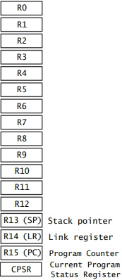
R0 - R12 are general purpose registers.
R13 is also called the stack pointer. It points to the top element of the stack.
R14 is also called the link register. It is used to store the return location for functions.
R15 is also called the program counter. It points to the next address being fetched from memory.
The CPSR holds flags that indicate the results of arithmetic and logic operations. The CPSR has the following 32 bits.
M (bits 0-4) is the processor mode bits.
T (bit 5) is the Thumb state bit.
F (bit 6) is the FIQ disable bit.
I (bit 7) is the IRQ disable bit.
A (bit 8) is the imprecise data abort disable bit.
E (bit 9) is the data endianness bit.
IT (bits 10-15 and 25-26) is the if-then state bits.
GE (bits 16-19) is the greater-than-or-equal-to bits.
DNM (bits 20-23) is the do not modify bits.
J (bit 24) is the Java state bit.
Q (bit 27) is the sticky overflow bit.
V (bit 28) is the overflow bit.
C (bit 29) is the carry/borrow/extend bit.
Z (bit 30) is the zero bit.
N (bit 31) is the negative/less than bit.
The most useful part of the CPSR for a programmer is the four status bits, negative (N), zero (Z), carry (C), and overflow (O). These bits can be tested and used for conditional execution of subsequent instructions. This register is set automatically during every arithmetic, logical, or shift operation. The four bits of the CPSR holding information about the results of a arithmetic or logical operation:
• The overflow (V) bit is set when an arithmetic operation results in an overflow.
• The carry (C) bit is set when there is a carry out of the operation.
• The zero (Z) bit is set when every bit of the result is zero.
• The negative (N) bit is set when the result is negative in two's-complement arithmetic.
These bits can be used to check the results of an arithmetic operation or logical operation, However, if a chain of arithmetic or logical operations is performed they must be checked at each step because the next operation changes the CPSR values.

More Computer Architecture Articles:
• CPU Cache Basics
• Introduction to Boolean Algebra
• Arduino Microcontroller Development Platform
• Digital Logic Transfer Characteristics
• How Computer Memory Works
• CPU Chip Packaging
• AMD's Phenom Processor
• Operating System Memory Allocation Methods
• Operating System Services
• Binary Number Representation and Binary Math