Hantek DSO5102P USB Storage Oscilloscope
2 Channels 100MHz 1GSa/s
Although the signals in a digital circuits are voltages, in most cases they are changing too fast for a voltmeter to be able to acquire any useful information. The oscilloscope is an instrument that displays digital signals on a line graph with time on the horizontal axis and voltage on the vertical axis. I often refer to an oscilloscope as the electronics technicians or engineers eyes. It will be difficult to do digital logic design without the use of an oscilloscope.
Oscilloscopes come in analog and digital versions. An analog oscilloscope uses analog circuitry to display the screen. This was the most common type of oscilloscope back when they used cathode ray tubes for displays. Today, oscilloscopes use LCD or LED screens. The fact that the signal is converted to digital data for display presents the ability for the oscilloscope to store the signal digitally, for that reason today's oscilloscopes are usually digital storage oscilloscopes.
One of the main features of an oscilloscope is the number of input channels. Each channel requires a probe to connect to a signal point. Each probe also has a ground clip. The signals displayed on the oscilloscope screen are voltages relative to the circuit ground. You usually need a minimum of two input channels because you are studying the relationship between two signals. Oscilloscopes come with one to four channels. An instrument with more than four input channels is usually called a logic analyzer.
It would be nice if digital signals were always perfectly square, but in the real world there are certain parasitic properties that tend to distort the shape of electronic signals. Three properties that affect signals are resistance, inductance and capacitance. Together they create a property called impedance. You can't totally avoid these parasitic properties in an electronic circuit. On the other hand, you don't want to hang an oscilloscope probe on the circuit that makes matters worse. The higher the impedance, the less the signal is distorted, therefore oscilloscope inputs and probes are made high impedance.
One specification that is related to oscilloscope input impedance, and to the quality of the circuitry of which the oscilloscope circuitry is constructed is bandwidth. The bandwidth of a circuit is the frequency at which the signal is half-attenuated (sometimes called the 3 dB (decibel) point. Without going into a long explanation, you want an oscilloscope with a high bandwidth, otherwise it will not be able to accurately display high-speed signals or fast rise and fall times.
Oscilloscope bandwidths range between 30 MHz and several hundred MHz. High bandwidth capability adds considerable cost to an oscilloscope, so it's best to determine what bandwidth you'll need for your work, or what bandwidth you're willing to pay for.
If signal storage is important to you, you should pay attention to the instruments maximum sampling rate. sampling rates range from 1 GS/s (Giga Samples per second) to 60 GS/s per channel. Also consider the length of signals it can store, usually stated as Kpts (thousands of data points per second), which relates to how much memory there is in the oscilloscope.

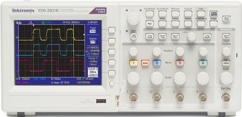
Tektronix TDS2024C 200 MHz
4 Channel, Oscilloscope, 2 GS/s Sampling,
More Computer Architecture Articles:
• Logical Versus Physical Memory Addresses
• Multithreaded Programming Process' and Threads
• Microprocessor Counter, Clock, Timer Circuits
• Operating System Process Control Block
• Capacitors in AC Circuits
• The Computer's Chipset
• Using the Microcontroller Timers
• Microcontroller's Parallel I/O System
• The Microcontroller's Asynchronous Serial Interface
• Introduction to Microprocessor Programming


