Work is accomplished in an electric circuit as the result of electron current flow. Current flow is produced by a power source, such as a battery, in the circuit. A power source has a potential difference across it, a voltage, across its terminals. Electrons flow from the more negative terminal to the less negative terminal in an attempt to reduce the potential difference.
A proper circuit has some resistance in it. If the circuit does not make a complete path, it is an open circuit, so no current can flow. If the circuit does not have some resistance in it (zero resistance), it is a Short circuit and current flow will be infinite (or whatever maximum the battery is able to provide).

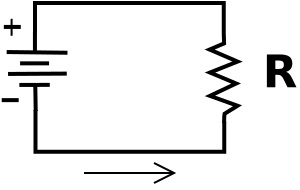
In the above diagram, the symbol on the left is the power source. Let's say the power source has a voltage, or potential difference across it of 10 Volts. Then because the resistor R is connected directly across the power source, it also has 10 volts across it.
Let's say the resistor has a resistance of 100 ohms. The current through the circuit can be calculated by Ohm's law: I = E/R (current in amps equals voltage in volts divided by resistance in ohms). Then the current would be 10/100, or 0.1 amps (100 milliamperes).
Series Circuits

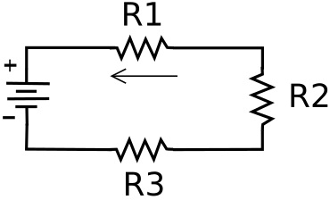
In a series circuit electronic devices or loads are connected in a chain so that current has to pass through every load. Since the loads are in series, the current is the same in all parts of the circuit. That current can be calculated by adding the resistances of all the loads and then using Ohm's law.
Again. let's say the power source is 10 volts. Let's give the resistors values of R1 = 120 ohms, R2 = 100 ohms, R3 = 180 ohms. So the total series resistance would be 400 ohms. Using Ohm's law: I = E/R, I = 10/400. The current would be .025 amps (25 milliamperes).
However, because the loads each have different resistances, the voltage drop across each load is different. The voltage accross each load can be calculated by Ohm's law E = I x R.
The voltage across R1 would be .025 x 120 = 3 volts.
The voltage across R2 would be .025 x 100 = 2.5 volts.
The voltage across R3 would be .025 x 180 = 4.5 volts.
Note that because all three resistors in series are connected accross the 10 volt power source, the sum of the voltage drops accross all the resistors must add up to 10 volts.
Parallel Circuits

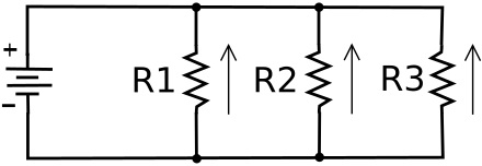
In a parallel circuit devices or loads are each connected separately accross the power source. Since the loads are in parallel, the voltage across each load is tha same. However, because because the loads each have different resistance, the current flow through each parallel path, or branch, is different. The current through each path can be calculated using Ohm's law: I = E/R.
Again, let's say the power source is 10 volts. Let's give the resistors values of R1 = 200 ohms, R2 = 100 ohms, R3 = 250 ohms.
The current through R1 would be 10/200 = .05 amps.
The current through R2 would be 10/100 = .10 amps.
The current through R3 would be 10/250 = .04 amps.
Note that the total current through the circuit is the sum of all the currents through the parallel paths; It = .05 + .10 + .04 = .19 amps.
There is an interesting formula to calculate the equivalent resistance of resistors in parallel; the reciprocal of the equivalent resistance is the sum of the reciprocals of the resistances of the parallel resistors.
1/Re = 1/R1 + 1/R2 + 1/R3
So in the above circuit, 1/Re = 1/200 + 1/100 + 1/250 ; 1/Re = .005 + .01 + .004 ; 1/.019 = 52.63 ohms.
Using Ohm's law to calculate the total current through the parallel resistor network, I = E/R; I = 10/52.63, I = .19 amps.
Series Parallel Circuits

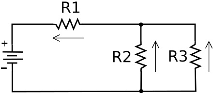
In a series parallel circuit, loads connected in parallel may be connected in series with another load or loads - or - loads connected in series may be connected in parallel with another load or loads. To solve a series parallel circuit you have to calculate the equivalent resistance of a parallel branch, and then use that value as if the branch was a single series load.
In the series parallel circuit above, let's say the power source is 10 Volts. Let's give the resistors values of R1 = 100 ohms, R2 = 200 ohms, R3 = 400 ohms.
Here's how we calculate the various currents and voltages in this circuit:
First calculate the equivalent resistance of the parallel part of the circuit (R2 and R3).
1/Re = 1/R2 + 1/R3
1/Re = 1/200 + 1/400
1/Re = .005 + .0025
1/.0075 = 133 ohms.
The parallel part of the circuit is in series with R1, so the sum of the series resistances is 133 ohms + 100 ohms = 233 ohms.
Using Ohm's law to calculate the total current through the circuit:
I = E/R; I = 10/233; I = .043 amps.
Using Ohm's law E = I x R to calculate the voltage drop across each resistor:
E R1 = .043 x 100 = 4.3 volts.
E R2 || R3 (parallel network) = .043 x 133 = 5.7 volts
Now, adding the two series voltage drops: 4.3 + 5.7 = 10.0 volts, the same as power source, so our calculations are correct.
Using Ohm's law, along with the reciprocal formula to calculate the equivalent resistance of resistors in parallel, you can calculate the voltage or current in any part of a circuit.
More Computer Architecture Articles:
• Round-Robin CPU Scheduling Algorithm
• Using The I2C Bus
• The AMD Athlon 64 Processor
• Introduction to Microprocessor Programming
• Getting started with Raspberry Pi
• Digital Logic Semiconductor Families
• The Motherboard Chipset
• Intel Celeron D Processor
• AMD's Phenom Processor
• Multi-Processor Scheduling

