

Peripheral Interfaces
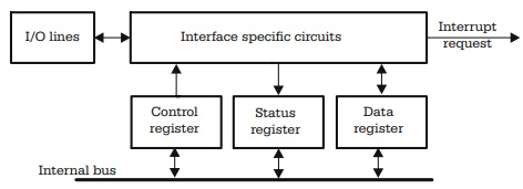
Microcontrollers are designed to be embedded in larger systems, and therefore they must be able to interact with the outside world. This interaction is possible by means of the peripheral interfaces. The general structure of a peripheral interface is shown in Fig. 1.6.
Depending on the complexity of the specific circuits to be controlled by the program, any peripheral interface contains one or more control and status registers, and one or more data registers. These registers are normally located in the address space of the data memory, and are accessed as RAM locations.
The most common peripheral interfaces, present in almost all the usual microcontrollers, are:
• The I/O (Input/Output) ports.
• The asynchronous serial interface (SCI, UART)
• The synchronous serial interface (SPI)
• Several types of timers
• The analog to digital (A/D) converters
The following chapters contain detailed descriptions of each of the above peripheral interfaces. Most of the peripheral interfaces have a common feature, which is the capability to generate interrupt requests to the CPU, when some specific events occur. This feature is analyzed in the next paragraph.
General Description of the Interrupt System
Most of the events related to the peripheral interfaces, like the change of status of an input line, or reception of a character on the serial communication line, are asynchronous to the program running on the CPU. There are two possible ways to inform the CPU about these events:
• One solution is to write the program so that it periodically tests the status of some
flags associated with the external events. This technique is called polling.
• The other solution is to interrupt the main program and execute a special subroutine
when the external event occurs.
An interrupt is a mechanism that allows an external event to temporarily put on hold the normal execution of the program, forcing the execution of a specific subroutine. Once the interrupt service subroutine completes, the main program continues from the point where it was interrupted.
At the CPU level, this mechanism involves the following steps:
1. The identification of the interrupt source. This is automatically done by hardware.
2. Saving the current value of the PC register, thus providing a means to return from the interrupt service routine. The contents of PC are saved to the stack, and the operation is also done by hardware.
3. Then, the PC is loaded either with, or from, the address of a reserved memory area, called the interrupt vector. For each possible interrupt, a unique vector is assigned. The interrupt vectors are hardwired and cannot be modified by the user.
4. At the address of the interrupt vector, the program must contain either the address of the interrupt service routine (HC11 uses this technique) or an instruction for an unconditional jump to this routine (AVR and 8051 work this way).
5. The next step is the execution of the Interrupt Service Routine (ISR). This is a program sequence similar to a subroutine, but ending with a special instruction called Return from Interrupt (RTI, RETI). To make sure that the main program is continued exactly from the status it had in the moment when the interrupt occurred, it is crucial that all the CPU registers used by the interrupt service routine are saved at the beginning of the ISR, and restored before returning to the main program. Some microcontrollers, like the HC11 family, are provided with a hardware mechanism to save the whole CPU status, upon reception of an interrupt request. The status is restored by the instruction RTI (Return from Interrupt) before the actual return to the main program. In all other cases, it is the user's responsibility to save and restore the CPU status in the interrupt service routine.
6. The final step in handling an interrupt is the actual return to the main program. This is done by executing a RTI (RETI) instruction as mentioned before. When this instruction is encountered, the contents of PC, saved in step 2, are retrieved from the stack and restored, which is equivalent to a jump to the point where the program was interrupted. The process of returning from an ISR is similar to returning from a regular subroutine, but there is an important difference: the interrupt service routines cannot be interrupted, and therefore once an interrupt has been acknowledged, further interrupts are automatically disabled. They are re-enabled by the RTI (RETI) instruction. All interrupts occurring during the execution of an ISR are queued and will be handled one by one, once the ISR is serviced.
The software control over the interrupt system is exerted either globally, by enabling/disabling all the interrupts by means of specific instructions, or individually, by setting or clearing some control bits, called interrupt masks, associated with each interrupt. In other words, the process of generating an interrupt request is double conditioned, as shown in Fig. 1.7.
Fig. 1.7. Double conditioning of interrupt requests.
The INTERRUPT FLAG is the actual interrupt source, and, usually, is a flip-flop set by the external event. This bit is, in most cases, accessible for the program as a distinct bit in the status register of the peripheral interface. The LOCAL INTERRUPT MASKS are control bits, located in the control registers of the interface. When set to 1 by software, the interrupts from that specific interface are enabled.
The GLOBAL INTERRUPT MASK is a bit located in the CPU status register (CCR, SREG, PSW) that enables or disables all interrupts.
In some cases, it is required that the CPU is informed immediately about certain important internal or external events, regardless of the status of the global interrupt mask. The solution to this problem is the non-maskable interrupt, which is unconditionally transmitted to the CPU. A special case of non-maskable interrupt can be considered the RESET. Basically, the behavior of the MCU at RESET is entirely similar to the process of identification and execution of a non-maskable interrupt.
Distinctive Features of the Interrupt System of HC11
The most important feature of the interrupt system of HC11 is that the CPU status is automatically saved by hardware, right after the PC is saved. This feature simplifies the programmer's work, but it wastes time saving and restoring all CPU registers. In most cases, the interrupt service routine does not use all the CPU registers, but needs to be executed as fast as possible.
The global control of the interrupt system is performed by means of the I bit in the CCR register. When I = 1, all maskable interrupts are disabled. When I = 0, the interrupts coming from a specific peripheral interface are enabled if the local mask associated with that interface is set to 1. The I bit can be controlled by means of the instructions SEI (Set Interrupt Mask) equivalent to Disable Interrupts, and CLI (Clear Interrupt Mask), equivalent to Enable Interrupts.
Besides the maskable interrupts, HC11 has three non-maskable interrupts, without counting the three possible RESET conditions (activation of the external RESET line, clock monitor fail reset, and watchdog reset). These are: XIRQ - External non-maskable interrupt, ILLOP - Illegal opcode trap, and SWI - software interrupt.
The XIRQ interrupt is generated upon detection of a logic level LOW on the XIRQ input line, if the X bit in CCR is clear. The X bit acts similarly to I, but it only affects the XIRQ interrupt, and it is not affected by the SEI and CLI instructions. The only way the user can alter the status of this bit is by the TAP (Transfer A to CCR) instruction.
The illegal opcode trap is an internal interrupt generated when an unknown opcode is fetched and decoded into the CPU. A software interrupt is generated when the instruction SWI is decoded. This is useful for defining breakpoints in a program for debug purposes.
The priority of the interrupts is hardwired. However, it is possible to define one of the interrupts as the highest priority non-maskable interrupt. For this purpose, the bits [PSEL3-PSEL0] (Priority Select bits) in register HPRIO (Highest Priority Interrupt Register) code the interrupt with the highest priority.
The vector area for HC11 is located at the end of the address space between the addresses $FFC0-$FFFF. See the data sheets for the list of exact addresses assigned to each interrupt vector.
Distinctive Features of the Interrupt System of AVR
The most important feature of the interrupt system of HC11 is that the CPU status is automatically saved by hardware, right after the PC is saved. This feature simplifies the programmer's work, but it wastes time saving and restoring all CPU registers. In most cases, the interrupt service routine does not use all the CPU registers, but needs to be executed as fast as possible.
The global control of the interrupt system is performed by means of the I bit in the CCR register. When I = 1, all maskable interrupts are disabled. When I = 0, the interrupts coming from a specific peripheral interface are enabled if the local mask associated with that interface is set to 1. The I bit can be controlled by means of the instructions SEI (Set Interrupt Mask) equivalent to Disable Interrupts, and CLI (Clear Interrupt Mask), equivalent to Enable Interrupts.
Besides the maskable interrupts, HC11 has three non-maskable interrupts, without counting the three possible RESET conditions (activation of the external RESET line, clock monitor fail reset, and watchdog reset). These are: XIRQ - External non-maskable interrupt, ILLOP - Illegal opcode trap, and SWI - software interrupt. The XIRQ interrupt is generated upon detection of a logic level LOW on the XIRQ input line, if the X bit in CCR is clear. The X bit acts similarly to I, but it only affects the XIRQ interrupt, and it is not affected by the SEI and CLI instructions. The only way the user can alter the status of this bit is by the TAP (Transfer A to CCR) instruction.
The illegal opcode trap is an internal interrupt generated when an unknown opcode is fetched and decoded into the CPU.
A software interrupt is generated when the instruction SWI is decoded. This is useful for defining breakpoints in a program for debug purposes. The priority of the interrupts is hardwired. However, it is possible to define one of the interrupts as the highest priority non-maskable interrupt. For this purpose, the bits [PSEL3-PSEL0] (Priority Select bits) in register HPRIO (Highest Priority Interrupt Register) code the interrupt with the highest priority.
The vector area for HC11 is located at the end of the address space between the addresses $FFC0-$FFFF. See the data sheets for the list of exact addresses assigned to each interrupt vector.
Distinctive Features of the Interrupt System of AVR
There are a few differences between the interrupt system of AT90S8535 and that of HC11. They are listed below:
• The interrupt vector does not contain the address of the interrupt service routine,
but a jump instruction to that routine.
• The vector area is located at the beginning of the program memory address space,
between the addresses $0000 and $0010.
• There are no non-maskable interrupts besides RESET.
• The I bit in SREG acts differently, compared to HC11: when I = 1, the interrupts are enabled.
• There is no equivalent to the HPRIO register, and no other means to modify the
hardwired relative priority of interrupts.
Distinctive Features of the Interrupt System of 8051
8051 has only five possible interrupt sources, compared to 16 for AVR, and 18 for HC11. The vectors are placed at the beginning of the program memory address space and must be initialized by the software to contain a jump to the interrupt service routine.
The interrupts are enabled and disabled according to the same principles described for HC11 and AVR. The difference is that all the control bits associated with the interrupt system are placed in a Special Function Register (SFR) called IE (Interrupt Enable register) located at the address A8h. This register contains the global interrupt control bit, called in this case EA (Enable All interrupts), and bits to enable each individual interrupt.
One interesting distinctive feature of the interrupt system of 8051 is the possibility to choose between two priority levels (low and high) for each interrupt. To this purpose, a special register called IP (Interrupt Priority register) contains a bit associated with each interrupt. When the priority bit is 0, the associated interrupt has a low priority level, and when the priority bit is 1, the interrupt has high priority. Unlike HC11 and AVR, for 8051 a high-priority interrupt can interrupt a low-priority interrupt service routine.
The 8051 does not save the CPU status automatically, therefore the interrupt service routine must save and restore the registers used, including PSW.
About Microcontrollers in Practice

The book is structured into three sections. Chapters 1-8 aim to create a detailed overview of microcontrollers, by presenting their subsystems starting from a general functional block diagram, valid for most microcontrollers on the market. In each case, we describe the distinctive features of that specific subsystem for HC11, 8051 and AVR. This whole section has a more theoretical approach, but, even here, many practical examples are presented, mainly regarding the initializations required by each subsystem, or the particular use of the associated interrupts. The purpose of this section is to create a perspective that views the microcontroller as a set of resources, easy to identify and use.
Chapters 9-16 contain eight complete projects, described from the initial idea, to the printed circuit board and detailed software implementation. Here too, we permanently focus on the similarities between the microcontrollers discussed, from the hardware and software perspectives.
All chapters contain exercises, suggesting modifications or improvements of the examples in the book. Most exercises have solutions in the book; for the others the solutions can be found on the accompanying CD.
Finally, the appendices contain additional information intended to help the reader to fully understand all the aspects of the projects described in the previous sections. We chose to present these details separately in these appendices, in order to avoid fragmentation of the flow of the main text.
Stressing common characteristics and real applications of the most used microcontrollers, this practical guide provides readers with hands-on knowledge of how to implement three families of microcontrollers (HC11, AVR, and 8051). Unlike the rest of the ocean of literature on individual chips, Microcontrollers in Practice supplies side-by-side comparisons and an overview that treats the systems as resources available for implementation. Packed with hundreds of practical examples and exercises to foster mastery of concepts and details, the guide also includes several extended projects. By treating the less expensive 8-bit and RISC microcontrollers, this information-dense manual equips students and home-experimenters with the know-how to put these devices into operation. Click here to learn more.

More Computer Architecture Articles:
• Operating System File Management
• Online Color Coded Resistor Calculator
• Getting started with Raspberry Pi
• Logical Versus Physical Memory Addresses
• Operating System Memory Management
• Multicore Programming
• Microcontroller Registers
• Binary Floating-Point Numbers
• Basic Computer Architecture
• Capacitors in DC Circuits