In early computers, all data transfers to and from a device such as a disk drive, graphics card, network card or sound card, and main memory were routed through a CPU register. This is called Programmed Input Output (PIO). It requires the processor to read and write single words from memory until the entire data transfer is complete. This is inefficient use of CPU cycles.
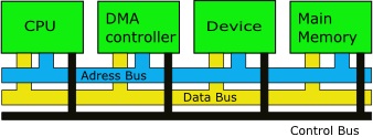
With DMA, the DMA controller chip takes control of the system buses to move data between the device and main memory. The CPU initiates the DMA transfer, and receives an interrupt from the DMA controller when the operation is complete, but the CPU is not involved with each single word of the transfer.

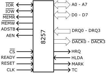
When a device requests service, it asserts its associated request line (DRQ1 to DRQ3), signaling the DMA controller. The DMA controller then asserts the HRQ (Hold Request) signal to the CPU. Once the CPU has reached a state where it can release the bus, all the signals normally controlled by the CPU (MEMR, MEMW, IOR, IOW) are placed in tri-state mode. Then the CPU asserts the HLDA (Hold Acknowledge) signal which tells the DMA controller that it can now take control of the bus.
The DMA controller asserts the DACK (DMA Acknowledge) signal of the device that requested the transfer to inform it that the transfer is commencing. The DMA controller now operates the MEMR, MEMW, IOR, IOW signals and performs the transfer. When the transfer is complete, the device requesting the service will de-assert it's DRQ line.
If none of the other channels have their DRQ lines asserted, the DMA controller will tri-state the MEMR, MEMW, IOR,-IOW and bus signals. Then it will de-assert the HRQ signal to the CPU. The CPU will de-assert the HLDA signal, retake control of the MEMR, MEMW, IOR, IOW and bus lines, and resume executing instructions.
DMA Modes
Burst Mode
In burst mode (also called block transfer mode) an entire block of data is transferred in one contiguous operation. Once the DMA controller takes control of the system bus it transfers all data in the data block before releasing control of the system bus back to the CPU. This is the most efficient method of transfer, but it leaves the CPU inactive for relatively long periods of time.
Cycle Stealing Mode
In the cycle stealing mode, the DMA controller takes control of the system bus, transfers one byte of data, releases control of the system bus back to the CPU, takes control of the system bus, transfers one byte of data, continually obtaining and releasing control of the system bus, transferring one byte of data per access until the entire block of data has been transferred.
By repeatedly taking and releasing control of the system bus, the DMA controller essentially interleaves data transfers with CPU instruction processing. The CPU is not left inactive for as long as in burst mode, However the data block is not transferred as quickly as in burst mode.
Transparent Mode
In the transparent mode the DMA controller transfers data only when the CPU is performing operations that do not use the system bus. This way the DMA transfer never interferes with the CPU executing its programs. The disadvantage of transparent mode is complexity of determining when the CPU is not using the system bus. This can be inefficient in terms of overall system performance.
8237 DMA Controller

The 8237 DMA controller was used in the original IBM PC and IBM XT. The 8237 has four-channels, each capable of DMA transfers at rates of up to 1.6 MB/s. Each channel is capable of addressing and transferring a full 64k-byte section of memory.

With the PC AT, another 8237 was added in master-slave configuration, increasing the number of DMA channels from four to seven. Today's PCs have a chipset that emulates the 8237 for backward compatibility.
Standard ISA DMA Assignments
0 DRAM Refresh
1 User hardware
2 Floppy disk controller
3 Hard disk controller
4 DMA chip cascade
5 User hardware
6 User hardware
7 User hardware
In early computers you had to manually set the DMA channels for non-standard devices like a video card or a sound card using jumpers on the device.
In the PCI bus architecture, unlike ISA, has no central DMA controller. Instead, any PCI compliant device can request bus ownership from the PCI bus controller (in the southbridge) and become the "bus master". Since only one device can be bus master at one time, if several devices request bus ownership simultaneously, the PCI bus controller will arbitrate which will take control of the bus.
More Computer Architecture Articles:
• Monolithic Kernel vs Microkernel vs Hybrid Kernel
• Microprocessor Counter, Clock, Timer Circuits
• Capacitors in DC Circuits
• Processor Affinity in Symmetric Multiprocessing
• Basic Electronics for Computer Architecture
• Arduino Microcontroller Development Platform
• AMD's Microarchitectures
• Learn Assembly Language Programming on Raspberry Pi 400
• Simplified Windows Architecture Overview
• Microcontroller Registers

