Although a microprocessor contains an ALU (Arithmetic Logic Unit) and may also contain audio and graphics processing circuitry, it is primarily a programmable device. This allows it to perform multiple logic and control functions without changing its physical structure. Because of this, its difficult to understand computer architecture without getting into its programming.
When programming a microprocessor, it understands only binary 0s and 1s. Programs containing only binary 0s and 1s are said to be in "machine language". However humans have difficulty understanding machine language. If we express the binary 0s and 1s using mnemonics and hexadecimal encoding, it becomes somewhat easier for humans to understand. This encoding results in what is called "assembly language". However, since a microprocessor understands only binary, the assembly code must be converted into binary code before it is stored or processed by microprocessor.
In order to make programming easier to understand, many "high level" languages have been developed. These languages are closer to human language and so the code is easier to understand. Programming languages that are very easy for humans to understand and program with, like Python, are called "higher" than languages that are less easy for humans to understand, like C.
However the higher the language, the lower it's performance. Any programming language higher than assembly language hides the underlying binary code and microprocessor architecture to such an extent that its useless to use for learning computer architecture. So in this book, we'll use only assembly language and machine language.
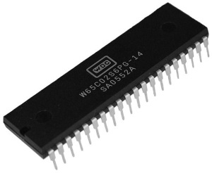
Today's multi-core 64-bit microprocessors have an extremely complex architecture, so it would be very difficult to start learning microprocessor programming using one of these microprocessors. Even today's 8-bit microcontrollers, have complex programming modes and architecture. And so, in seeking to make learning as easy as possible, we'll first learn how to program a more simple microprocessor, one of the first 8-bit microprocessors, the 6502.
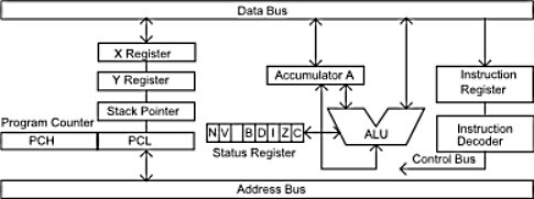
Simplified 6502 Block Diagram
The 6502 is an 8-bit microprocessor that was introduced in 1975. It was used in video game consoles like Atari and Nintendo, and in early home computers like the Apple II and Commodore 64. The 6502 has an 8-bit ALU, a 16-bit program counter, an 8-bit stack pointer, a 6 flag status register, and two 8-bit general purpose registers (X and Y).
As stated above, assembly language involves using instructions that are mnemonics called opcodes, along with values and/or addresses in hexadecimal notation. Shown below is an assembly language statement to load the accumulator register with the hex value c0. In this instruction the # sign means the value to load is given in the instruction itself, and the $ sign means it's a hexadecimal value.
LDA #$c0
Shown below is an assembly language statement to store the current value in the accumulator register to the memeory location with the address hex 3E32.
STA $3E32
Now that I've introduced a couple instructions, you can probably imagine how boring it could get if I just kept introducing instructions with no opportunity for you to get actual hands-on experience programming 6502 assembly language. You could build a prototype board and start experimenting with an actual 6502 microprocessor. That would be cool, but would require too much work.
Fortunately Nick Morgan (screen name Skilldrick) has created a 6502 assembly language simulator. Amazingly, he programmed this application in JavaScript (which means it easily runs in your web browser). And even more Amazingly, he released it free under a GNU General Public License. I will be using that application to demonstrate more 6502 assembly language instructions and programming concepts.
I would recommend that you grab a copy of the Skilldrick 6502 assembly language simulator and use it for hands-on simulated programming to follow along with this material and other code examples that you find on the internet. It can be found at: https://github.com/skilldrick/6502js.
Shown below is an example of using the Skilldrick simulator to run an assembly language consisting of only the two instructions shown mentioned above.
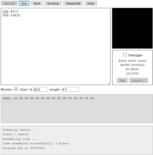
After entering the two instructions into the text box, check the box next to Monitor and, in the text box next to Start:, enter the memory location 3E32. Then click on the [Assemble] button. Assuming the application returned the results "code assembled successfully", next click on the [Run] button.
Note in the box on the right that the Accumulator A now contains the value $c0, and in the memory Monitor box, the location 3E32 contains the value c0.
Addressing Modes
At this point, it would be appropriate to introduce the concept of Addressing Modes. An addressing mode defines how instructions interpret the operand(s) the instruction. It specifies how to calculate the effective memory address of an operand by using information held in registers and/or in the instruction.
The instruction LDA #$c0 uses the Immediate addressing mode, which means that no offsets, addresses or values need to be calculated, the value to be used is the operand within the instruction itself.
The instruction STA $3E32 uses the Absolute addressing mode, which means that no offsets, addresses or values need to be calculated, the address to be used is the operand within the instruction itself.
An important thing to mention at this point is to note that, after you assemble but before you run our little program the instruction pointer, PC= in the box on the right, contains the address $0600. If you where to click the [Hexdump] button at this point, you would see 0600: a9 c0 8d 32 3e. This is the actual machine code of the program. The code for LDA is a9. The code for STA is 8d. But note that the machine code for the STA operand is 32 3e, while our assembly code for the STA operand is 3e32. This is because the 6502 is a little endian machine, which means that 2 byte values are stored with the LSB first.
Indexed Indirect Addressing Mode
An indexed addressing instruction uses the X or Y register as an offset to the address being accessed. shown below is an example of a load accumulator instruction using the indexed indirect addressing mode.
LDA ($B0,X)
Here's how it works:
1. First $B0 would be added to the contents of the X register. Let's assume the X register contains $04. The sum of $B0 and $04 would be $B4.
2. The value at this address together with the contents of the next address, make up a third address. So the computer would access memory address $B4 and $B5.
3. Let's assume memory address $B4 contains $FC, and memory address $B5 contains $1C. Since the 6502 is a little endian machine the computer would interpret the number found in $B4 and $B5 as $1CFC.
4. So the computer would load the accumulator with the value found at memory location $1CFC.
Shown below is the assembly code that you could use with the Skilldrick simulator to check the operation of the instruction.
LDA #$88
STA $1CFC
LDA #$FC
STA $B4
LDA #$1C
STA $B5
LDX #$04
LDA ($B0,X)
Note that all except the last instruction are used to set up the offset and values in memory in order for the example to work.
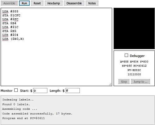
Shown above is the results of running the program. You could single-step the program, but the important thing is that it ends with the value $88 in the accumulator.
If you didn't quite follow this, don't worry, my purpose here was to demonstrate how complex, and powerful, some 6502 addressing modes can be. The Indexed Indirect Addressing Mode is rarely used.
Implicit Addressing Mode
Now that we've studied one of the most complicated 6502 addressing modes, let's look at one of the most simple. With implicit addressing mode (sometimes called "implied addressing mode") all you need is the opcode, you don't use an operand. The address or register it refers to is implied by the opcode itself. Shown below is an example of an instruction that uses implicit addressing mode.
INX
INX stands for Increment X Register. In other words, add one to the value is in the X register.
6502 Addressing Modes
Shown below is a complete list of 6502 addressing modes.
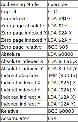
Zero Page Addressing
At this point I need to explain zero page addressing. Main memory is considered to divided into blocks or pages. Each page contains $ff (256 decimal) memory locations. Normally a memory location address requires two bytes (e.g $0803). Memory locations on the first page of memory (or zero page since computers always start counting with zero) range from from $0000 to $00FF. Since zero page addresses always start with 00, zero page instructions need only one-byte operands. If you were building a circuit that required 256 instructions or less, you could save a lot of program storage space by using only zero page instructions.
Assembly Language Decision Making
A microprocessor makes most decisions by comparing two or more values. To accomplish this, the compare instruction is used. There are three different compare instructions: CMP compares a value with the contents of the Accumulator, CPX compares a value with the contents of the X register, and CPY compares a value with the contents of the Y register. The compare instructions use the different addressing modes similar to other instructions.
Shown below is the example code to demonstrate the CMP instruction.
LDA #$11
CMP #$11
BEQ EQUAL
LDA #$44
BRK
EQUAL:
LDA #$88
This code loads the accumulator with the value $11 and then uses the CMP instruction to compare it with the value $11. If the two values are not equal, the next instruction loads the accumulator with the value $44. Then the BRK (BReaK) instruction stops program execution.
If the two values are equal, the BEQ (Branch if EQual) instruction causes the program flow to branch to the relative address EQUAL, where the next instruction loads the accumulator with the value $88.
So you can run the code in the Skilldrick simulator and check the resulting accumulator contents. Since the values are equal, the accumulator should end up containing the value $88. Then try changing one of the $11 values and run the program again. The accumulator should end up containing the value $44.
Branch instructions use relative addressing. With relative addressing you can provide an offset value to branch to, or you can give the assembler a label and it calculates and encodes an offset address to branch to. You don't need to know the address or do anything except provide the label.
The compare instructions subtract (without carry) an immediate value or the contents of a memory location from the indicated register. They don't save the result but they do set the status of the results in the Z and C flags of the Status Register.
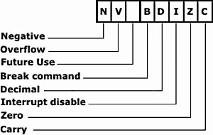
If the value in the indicated register is less than the comparison value the Z and C flags are set to 0. If the value in the indicated register is equal to the comparison value the Z and C flags are set to 1. If the value in the indicated register is greater than the comparison value the Z flag is set to 0 and the C flag is set to 1.
Compare Instruction Status Register Results
| Comparison Result | Z | C |
| Register < Memory | 0 | 0 |
| Register = Memory | 1 | 1 |
| Register > Memory | 0 | 1 |
Run the code in the Skilldrick simulator changing one of the $11 values and check how it effects the Status Register flags.
Assembly Language Program Loop
Computer programs use loops for creating time delays, searching a list, repeating a process, and many other functions. To create a loop, a compare instruction is used, along with a branch instruction. But what makes it a loop is the use of a Mathematical instruction.
The 6502 microprocessor mathematical instructions are ADC (Add to accumulator with Carry) and SBC (Subtract from accumulator with Carry). Also commonly used to create a loop are the Increment and Decrement instructions, which add 1 or subtract 1 from the value in the X or Y register, or the value in a memory location. The DEX instruction decrements the X register by 1.
Shown below is the example code to demonstrate using the DEX instruction to create a loop.
LDX #$08

LOOP:
DEX
CPX #$03
BNE LOOP
BRK
This code loads the X register with the value $08 and then uses the DEX instruction to decrement the X register by 1. Then it uses the CPX instruction to compare it with the value $03. If the DEX instruction has not decremented the value in the X register to $03, the BNE instruction sends program execution back to the DEX instruction until value in the X register is $03. Then program execution falls through to the BRK instruction.
You can run the code in the Skilldrick simulator and check the resulting X register contents. Then try changing one of the initial X register contents, or the compare value and run the program again, checking resulting X register contents. Also note the results in the Z and C flags of the Status Register.
Common 6502 Instructions
Shown below are some common 6502 assembly language instructions.
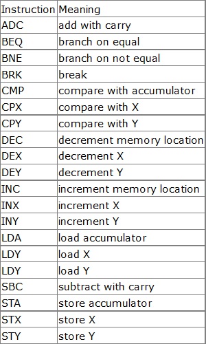
This section is a basic introduction to microprocessor programming using the 6502 microprocessor. There are many more 6502 assembly language instructions, and each instruction may use several different addressing modes. The 6502 is an old 8-bit microprocessor, although still very powerful and still available from electronic suppliers like Jameco Electronics (jameco.com) and Mouser Electronics (www.mouser.com). A search on the Internet will provide you with complete 6502 assembly language instructions, and an amazing amount of example code.
More Computer Architecture Articles:
• Learn Assembly Language Programming on Raspberry Pi 400
• How Computer Chips are Made
• Intel's Core i7 Processors
• Microcontroller Architectures
• AMD's Phenom Processor
• Operating System Memory Paging
• Introduction to Boolean Algebra
• Multi-Processor Scheduling
• The Android Operating System
• Intel's Dual-Core Core i3 Processor

