

The Analog Comparator
The simplest way for a microcontroller to interact with an analog signal is by using an analog comparator. It seems that all the information a comparator can offer about a signal is one bit, containing answer to the question whether the amplitude of the respective signal is or isn't higher than a certain threshold. In fact, it's not only the amplitude of the signal that counts the moments when the signal crosses the threshold are also important.
This paragraph presents the interface with the analog comparator of the AVR, an ingenious and flexible implementation. The block diagram of the interface is shown in Fig. 7.1
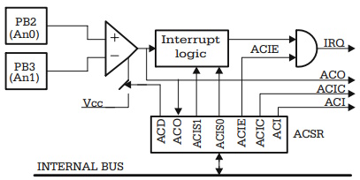
Fig. 7.1. Block diagram of the analog comparator interface of AT90S8535
The inputs of the comparator are connected to pins PB2, PB3 of the circuit. The corresponding lines of port B must be configured as inputs, with the internal pull-up resistors disabled.
The Control and Status Register ACSR
The bits in the Control and Status Register (ACSR) of the comparator offer the following control features:
• Control of the comparator's power supply, by means of the ACD (Analog
Comparator Disable) bit. Setting this bit to 1 disables the comparator.
• Read the status of the comparator's output in the ACO (Analog Comparator Output) bit.
• Select the event that triggers the interrupt mechanism by using the [ACIS1:ACIS0]
control bits (Analog Comparator Interrupt Mode Select). The event selected by
these bits sets the ACI flag (Analog Comparator Interrupt flag), which may
generate an interrupt request. Refer to Table 7.1 for a description of how the
events that set the ACI flag are related to the bits ACIS1:ACIS0.
• If the ACIC (Analog Comparator Input Capture Enable) control bit is set, the
output of the comparator ACO is directly connected to the control logic that
selects the input capture event for Timer1. In this case, the settings described in
Chap. 6 for the selection of the capture edge apply.
The configuration of the bits in the ACSR control and status register is as follows:
The ACI interrupt flag is erased by writing 1 in this position of the ACSR register, or by hardware, when the interrupt is executed.
Table 7.1. The effect of programming [ACIS1:ACIS0]
The General Structure of the A/D Converter Subsystem
An analog signal can be represented as a continuous amplitude-time function, which, in principle, can have any shape, as in the example shown Fig. 7.2.
The only way a digital system, like a microcontroller, can acquire information about the evolution of such a signal is to measure, at discrete time intervals (T1, T2, T3, T4, ... ), samples from the signal, which are converted to series of numerical values S1, S2, S3, S4, ... This measuring process is performed by the A/D converter.
Obviously, as the time between successive samples decreases, the resulted discrete signal better approximates the analog signal input. There is, however, a limit to the time between which two successive samples can be reduced, imposed by the conversion time, which is a constructive constant of the A/D converter, defined as the time required to obtain the numerical value of a sample of the analog signal.
An important parameter of the A/D converter is the resolution, defined as the number of bits of the result. The more bits are used for representing the number, the better is the accuracy of the representation.
Figure 7.3 shows the general block diagram of a typical A/D converter, as implemented in most microcontrollers.
Usually, a microcontroller has several analog inputs (eight, typically). The inputs are processed one by one, the selection being made by a multiplexer MUX, depending on the selection bits in the control register. The selected input is applied to a sample & hold (S & H) circuit, which retains the sampling value until the conversion is completed. The actual converter is of the "successive approximation" type, and comprises the SAR (Successive Approximation Register), a DAC (Digital to Analog Converter), and an analog comparator.
Fig. 7.2. Example of sampling an analog signal
Fig. 7.3. Block diagram of a typical ADC
The conversion result is delivered in an ADC data register, along with an End of Conversion Flag in the ADC status register. Optionally, the End of Conversion Flag can generate an interrupt.
About Microcontrollers in Practice

The book is structured into three sections. Chapters 1-8 aim to create a detailed overview of microcontrollers, by presenting their subsystems starting from a general functional block diagram, valid for most microcontrollers on the market. In each case, we describe the distinctive features of that specific subsystem for HC11, 8051 and AVR. This whole section has a more theoretical approach, but, even here, many practical examples are presented, mainly regarding the initializations required by each subsystem, or the particular use of the associated interrupts. The purpose of this section is to create a perspective that views the microcontroller as a set of resources, easy to identify and use.
Chapters 9-16 contain eight complete projects, described from the initial idea, to the printed circuit board and detailed software implementation. Here too, we permanently focus on the similarities between the microcontrollers discussed, from the hardware and software perspectives.
All chapters contain exercises, suggesting modifications or improvements of the examples in the book. Most exercises have solutions in the book; for the others the solutions can be found on the accompanying CD.
Finally, the appendices contain additional information intended to help the reader to fully understand all the aspects of the projects described in the previous sections. We chose to present these details separately in these appendices, in order to avoid fragmentation of the flow of the main text.
Stressing common characteristics and real applications of the most used microcontrollers, this practical guide provides readers with hands-on knowledge of how to implement three families of microcontrollers (HC11, AVR, and 8051). Unlike the rest of the ocean of literature on individual chips, Microcontrollers in Practice supplies side-by-side comparisons and an overview that treats the systems as resources available for implementation. Packed with hundreds of practical examples and exercises to foster mastery of concepts and details, the guide also includes several extended projects. By treating the less expensive 8-bit and RISC microcontrollers, this information-dense manual equips students and home-experimenters with the know-how to put these devices into operation. Click here to learn more.

More Computer Architecture Articles:
• Operating System Boot
• Microprocessor Counter, Clock, Timer Circuits
• CPU Process Scheduling
• Logical Versus Physical Memory Addresses
• Basic Decoder Circuitry
• Operating System Memory Page Sharing
• Binary Number Representation and Binary Math
• CPU Chip Packaging
• Operating System Process Scheduling Queues
• Digital Logic Semiconductor Families