

In many situations, is not enough for a microcontroller to measure analog signals - it is also required to generate analog signals. There is a variety of industrial equipment that is controlled by analog signals. To communicate with this type of equipment, the microcontroller system must be able to generate analog signals with precisely controlled amplitudes.
One simple way to do this is to use a PWM (Pulse Width Modulation) timer. By applying a PWM signal to a low-pass filter, the resulting output signal has the amplitude Vout = K x VM where VM is the amplitude of the VPWM signal, and K is the duty cycle (refer to Fig. 7.4).
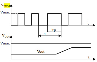
Fig. 7.4. The analog signal associated with a PWM signal
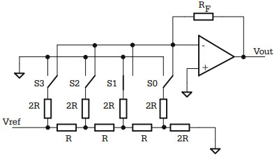
Fig. 7.5. Simplified schematic of a 4-bit DAC, using R-2R ladder network
In cases when a PWM timer is not available, or when the number of PWM channels is less than the required number of analog outputs, the solution is to use special external circuits, called Digital-to-Analog Converter, or DACs. There is a variety of such circuits with different resolutions (the number of bits of the converted word), different conversion time, or different ways to present the result (serial/parallel). The majority of them operate on the same principle, by dividing the current in a ladder type R-2R resistor network. The simplified schematic of a 4-bit DAC based on this principle is presented in Fig. 7.5.
In this circuit, the operational amplifier acts in such a way that the potential of the inverting input is maintained equal to the potential of the non-inverting input, which is connected directly to ground. As a consequence, regardless of the status of the switches S3-S0, the network acts as if all of the 2R resistors, have a terminal connected to ground. This means that the equivalent resistance that loads Vref is constant, equal to R, and the total absorbed current from Vref is also constant, Iref = Vref/R. The currents flowing through the four switches (S3, S2, S1, S0) are I3 = Iref/2, I2 = Iref/4, I1 = Iref/8, I0 = Iref/16. The output voltage is
Vout = -IF x RF
where IF is a fraction of Iref, directed by the switches S3-S0 to the inverting input of the operational amplifier,
IF = b3 x I3 + b2 x I2 + b1 x I1 + b0 x I0
IF = Iref(b0/2 + b1/4 + b2/8 + b3/16)
were (b3-b0) are the bits of the word that must be converted to an analog value.
It follows that the output voltage Vout is proportional to the binary value to be converted.A typical example of a circuit, built on this principle, is MX7224 from Maxim. The functional block diagram and the pin configuration of the circuit are shown in Fig. 7.6.
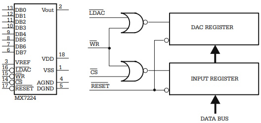
Fig. 7.6. Block diagram and pin configuration of a typical DAC IC
The circuit is designed so that it can be directly connected to a data bus. When both the CS\ and WR\ signals are active, the data from the bus is transferred to the Input Register. The LDAC\ signal controls the transfer of data to the DAC register. When CS\ = 0, WR\ = 0 and LDAC\ = 0, both registers are transparent and the data from the DB0–DB7 inputs is converted to Vout. With this configuration of the control signals the circuit can be directly connected on an output port of the microcontroller.
About Microcontrollers in Practice

The book is structured into three sections. Chapters 1-8 aim to create a detailed overview of microcontrollers, by presenting their subsystems starting from a general functional block diagram, valid for most microcontrollers on the market. In each case, we describe the distinctive features of that specific subsystem for HC11, 8051 and AVR. This whole section has a more theoretical approach, but, even here, many practical examples are presented, mainly regarding the initializations required by each subsystem, or the particular use of the associated interrupts. The purpose of this section is to create a perspective that views the microcontroller as a set of resources, easy to identify and use.
Chapters 9-16 contain eight complete projects, described from the initial idea, to the printed circuit board and detailed software implementation. Here too, we permanently focus on the similarities between the microcontrollers discussed, from the hardware and software perspectives.
All chapters contain exercises, suggesting modifications or improvements of the examples in the book. Most exercises have solutions in the book; for the others the solutions can be found on the accompanying CD.
Finally, the appendices contain additional information intended to help the reader to fully understand all the aspects of the projects described in the previous sections. We chose to present these details separately in these appendices, in order to avoid fragmentation of the flow of the main text.
Stressing common characteristics and real applications of the most used microcontrollers, this practical guide provides readers with hands-on knowledge of how to implement three families of microcontrollers (HC11, AVR, and 8051). Unlike the rest of the ocean of literature on individual chips, Microcontrollers in Practice supplies side-by-side comparisons and an overview that treats the systems as resources available for implementation. Packed with hundreds of practical examples and exercises to foster mastery of concepts and details, the guide also includes several extended projects. By treating the less expensive 8-bit and RISC microcontrollers, this information-dense manual equips students and home-experimenters with the know-how to put these devices into operation. Click here to learn more.

More Computer Architecture Articles:
• Basic Decoder Circuitry
• Round-Robin CPU Scheduling Algorithm
• Intel's Dual-Core Core i3 Processor
• The Microcontroller Memory Map
• Arduino Microcontroller Development Platform
• Multi-Processor Scheduling
• The Computer's Chipset
• Computer Video Display
• Fundamental Digital Logic Gates
• Binary Number Representation and Binary Math