

The General Structure and Functions of the Timer System
Timing is essential for the operation of microcontroller systems, either for generating signals with precisely determined duration, or for counting external events. For this reason, the timer subsystem is present in all microcontroller implementations, and covers a wide range of functions including:
• Generation of precise time intervals
• Measurement of duration of external events
• Counting external events.
Most microcontrollers are provided with dedicated timers, or use the general purpose timer to implement the following additional functions:
• Real time clock
• Generation of Pulse Width Modulated (PWM) signals
• Watchdog for detecting program runaway situations.
Although there are significant variations between different implementations of the general-purpose timer in different microcontrollers, there are many similarities in the principles of operation and the structure of the timer subsystem. Figure 6.1 shows a general block diagram of the timer system, illustrating the principles of implementation of most MCU timers.
The central element of the timer subsystem is a counter, TCNT (8 or 16-bits in length), which may be read or (sometimes) written by software. The clock for TCNT is obtained either from the system clock, divided by a programmable prescaler, or an external clock applied to one of the MCU pins. The software control upon the timer is performed by means of the control register TCTL and information regarding various events related to the timer may be read from the status register TFLG.
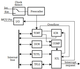
Fig. 6.1. General block diagram of the timer subsystem
Several operating modes are possible for the timer:
Timer overflow. In this mode, the event of interest is when the TCNT counter reaches its maximum count and returns to zero on the next clock pulse. The overflow signal that marks this event is applied to the interrupt control logic (ICL), which may generate an interrupt request to the CPU.
The time interval between two successive overflows is controlled either by modifying the frequency of the input clock applied to TCNT, or by writing to TCNT an initial value for counting.
• Input capture. In this operating mode, the contents of TCNT at the moment of the occurrence of an external event, defined by the edge of an input signal, is transferred in a capture register (ICR), and an interrupt request may be generated. By comparing two consecutive values capture by the ICR, it is possible to determine the time interval between the two external events.
• Output compare. In this operating mode, the contents of TCNT are continuously compared by hardware to the contents of the OCR (Output Compare Register) by means of the digital comparator COMP. When the contents of the two registers match, an interrupt request may be generated. Optionally, the compare match can be programmed to change the status of one or more output lines.
• External events counter. In this operating mode, the input of TCNT is connected to one of the MCU input lines, and TCNT counts the pulses associated with the external events. The software is informed about the recorded number of external events by reading TCNT.
Distinctive Features of the Timer System of the 8051 Microcontrollers
The timer of the 8051 family of microcontrollers does not have the output compare and the input capture features. In the standard configuration, there are two timers, named Timer0 and Timer1, each having as central element a 16-bit counter, called T0 and T1, respectively.
These are capable of counting, on an internal or external clock, and are accessible from the internal bus for read and write, as two 8-bit registers: TH0-L0 for Timer0, TH1-TL1 for Timer1.
The only event reported by timers to the CPU is the timer overflow condition. The logic diagram of the circuit for the clock selection and control is presented in the Fig. 6.2.
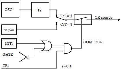
Fig. 6.2. Logic diagram of the clock control circuit for the 8051 timer
Description of the Timer Operating Mode 0
The logical diagram describing the 8051 timers operating in modes 0 and 1 is presented in Fig. 6.3. The only difference between mode 1 and mode 0 is that, in mode 1, the counter is 16-bit wide, and the overflow condition occurs at the transition from status $FFFF to $0000.
Description of the Timer Operating Mode 1
The logical diagram describing the 8051 timers operating in modes 0 and 1 is presented in Fig. 6.3. The only difference between mode 1 and mode 0 is that, in mode 1, the counter is 16-bit wide, and the overflow condition occurs at the transition from status $FFFF to $0000.
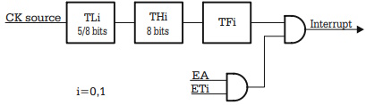
Fig. 6.3. 8051 timer in mode 0/1
Description of the Timer Operating Mode 2
In mode 2, the lower half of the counter (TLi) operates as an 8-bit counter, while the upper half (THi) acts as a register that holds the reload value for TLi. At overflow, the value written to THi is automatically transferred in TLi, and counting continues from this value. The logic diagram for the operating mode 2 of the 8051 timer is presented in Fig. 6.4. The clock source for the counter is selected as shown in Fig. 6.2.
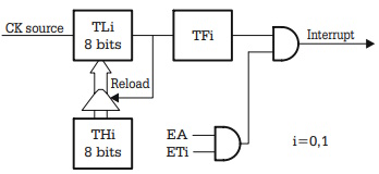
Fig. 6.4. The 8051 timer operating in mode 2
Description of the Timer Operating Mode 3
This operating mode is specific only for Timer0. In mode 3, the counter T0 is split into two 8-bit counters that count on different clocks. The lower half, TL0, operates in a way similar to modes 0, and 1, but the length of the counter is limited to 8 bits. At overflow, the flag TF0 is set, and an interrupt is generated if ET0 = 1.
The upper half of T0, called TH0, acts like a second 8-bit counter, which counts a fixed frequency fOSC/12 clock. At overflow, TF1 is set, and an interrupt can be generated if ET1 = 1. The logic diagram of the timer in this operating mode is presented in Fig. 6.5.
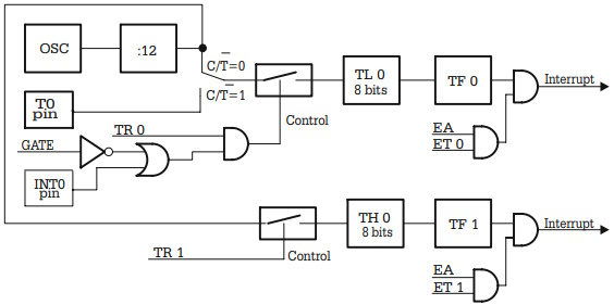
Fig. 6.5. The 8051 Timer in mode 3
PWM Timers. Principles of Operation
A PWM signal is, basically, a signal with the duty cycle dynamically controlled. If this signal is passed through a low-pass filter, the output of the filter is the analog signal VOUT = K x A, where A is the amplitude of the PWM pulses, and K is the duty cycle. This is a simple and cheap D/A converter, and therefore most recent microcontrollers include a dedicated PWM timer, or have the main timer designed with the capability to generate PWM signals.
The Motorola 68HC11 series K microcontrollers include a dedicated PWM timer, consisting of a free-running up-counter, PWCNT, whose content is permanently compared with two programmable registers, called PWPER and PWDTY. Refer to the block diagram of this timer, presented in Fig. 6.6.
PWPER defines the period of the output signal, and PWDTY controls the duty cycle of the PWM output. When the contents of the counter PWCNT match the contents of PWDTY, the control logic changes the polarity of the output signal, and when PWCNT reaches the value in PWPER, the counter is automatically cleared. The register PWCTL contains control bits to select the frequency of the input clock for PWCNT, the polarity of the output signal, and enable the entire PWM system.
The operation of the PWM timer is synthetically presented in Fig. 6.7. The series K microcontrollers 68HCHC11 include four 8-bit PWM channels. These can be configured to operate as two 16-bit PWM timers. The advantage of the structure presented in Fig. 6.6 is that it allows fine-tuning of the period of the output signal in a wide range.
The AVR family of microcontrollers uses Timer1 to generate PWM signals. The PWCNT counter is implemented using the least significant 8, 9, or 10 bits of TCNT1. There is no PWPER register, so that the period of the output signal can only be adjusted by selecting the frequency of the input clock.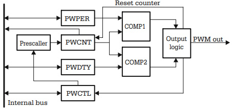
Fig. 6.6. Simplified block diagram of the PWM timer of 68HC11 series K
The length of the PWCNT counter is software selectable, by means of the bits [PWM11:PWM10] in register TCCR1A. The functions of the PWDTY register are executed by the OCR1 register. The difference is that when operating as a PWM timer, TCNT1 is forced to be reversible. It counts up from $0000 to a TOP value, determined by the length of the counter (8, 9, or 10 bits). When it reaches the TOP value, it starts counting down to zero. The polarity of the output signal is changed in opposite directions, when TCNT1 matches the value of OCR1 when counting upwards, and downwards. Refer to Fig. 6.8, and 6.9 for details of the operation of the PWM AVR timer.
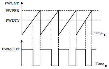
Fig. 6.7. Functional diagram of the PWM timer of 68HC11 series K
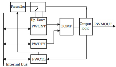
Fig. 6.8. Simplified block diagram of the PWM AVR timer
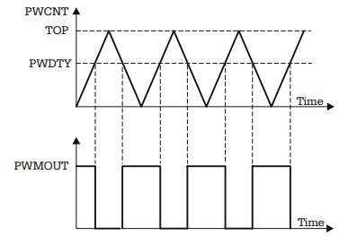
Fig. 6.9. Functional diagram of the PWM AVR timer
This PWM system is far less flexible than that of the HC11, but it is simple and cheap, so that it has been implemented in many AVR microcontrollers.
Watchdog Timers
The block diagram of a watchdog timer is presented in Fig. 6.10. The system consists of a counter, having the overflow time programmable in a range from a few milliseconds to a few seconds. When the watchdog overflows, a hardware RESET is generated.
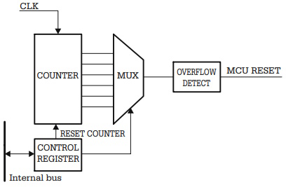
Fig. 6.10. Block diagram of the watchdog timer
If the watchdog is enabled, the program running on the microcontroller must be organized so that, periodically, at time intervals shorter than the overflow time, it resets the watchdog's counter, otherwise a hardware RESET is generated.
The control register is used to enable the watchdog, to select the overflow time, and to reset the counter.
About Microcontrollers in Practice

The book is structured into three sections. Chapters 1-8 aim to create a detailed overview of microcontrollers, by presenting their subsystems starting from a general functional block diagram, valid for most microcontrollers on the market. In each case, we describe the distinctive features of that specific subsystem for HC11, 8051 and AVR. This whole section has a more theoretical approach, but, even here, many practical examples are presented, mainly regarding the initializations required by each subsystem, or the particular use of the associated interrupts. The purpose of this section is to create a perspective that views the microcontroller as a set of resources, easy to identify and use.
Chapters 9-16 contain eight complete projects, described from the initial idea, to the printed circuit board and detailed software implementation. Here too, we permanently focus on the similarities between the microcontrollers discussed, from the hardware and software perspectives.
All chapters contain exercises, suggesting modifications or improvements of the examples in the book. Most exercises have solutions in the book; for the others the solutions can be found on the accompanying CD.
Finally, the appendices contain additional information intended to help the reader to fully understand all the aspects of the projects described in the previous sections. We chose to present these details separately in these appendices, in order to avoid fragmentation of the flow of the main text.
Stressing common characteristics and real applications of the most used microcontrollers, this practical guide provides readers with hands-on knowledge of how to implement three families of microcontrollers (HC11, AVR, and 8051). Unlike the rest of the ocean of literature on individual chips, Microcontrollers in Practice supplies side-by-side comparisons and an overview that treats the systems as resources available for implementation. Packed with hundreds of practical examples and exercises to foster mastery of concepts and details, the guide also includes several extended projects. By treating the less expensive 8-bit and RISC microcontrollers, this information-dense manual equips students and home-experimenters with the know-how to put these devices into operation. Click here to learn more.

More Computer Architecture Articles:
• Pentium P5 Processor
• The AMD Athlon 64 Processor
• AMD Sempron Processor
• Intel Celeron D Processor
• The Many Processes of Silicon Wafer Manufacturing
• Operating System Memory Allocation Methods
• Computer Buses
• ARM Cortex-A72 Registers
• Operating System Services
• The Android Operating System