

A microcontroller is a structure that integrates in a single chip a microprocessor, a certain amount of memory, and a number of peripheral interfaces. The Central Processing Unit (CPU) is connected to the other subsystems of the microcontroller by means of the address and data buses. Depending on how the CPU accesses the program memory, there are two possible architectures for microcontrollers, called Von Neumann, and Harvard.
Figure 1.1 shows the structure of a computer with Von Neumann architecture, where all the resources, including program memory, data memory, and I/O registers, are connected to the CPU by means of a unique address and data bus.
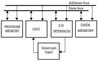
Fig. 1.1. Block diagram of Von Neumann architecture
A typical microcontroller having Von Neumann architecture is 68HC11 from Motorola. In HC11, all resources are identified by unique addresses in the same address space, and can be accessed using the same instructions. For example, in case of the instruction:
LDAA <address> ;load accumulator a from <address>
The operand indicated by the label <address> can be any of the microcontroller's resources, from I/O ports, to ROM constants. This way of accessing resources allows the existence of complex instructions like this:
ASL 35,x ;arithmetic shift left the memory

;location with the address

;obtained by adding 35 to the

;index register X.
Therefore, the Von Neumann microcontrollers tend to have a large instruction set, including some really complex instructions. This is the reason why computers having the Von Neumann architecture are often called CISC, or Complex Instruction Set Computers.
The main disadvantage of this architecture is that the more complex the instruction, the longer it takes to fetch, decode, execute it, and store the result. The instruction in the above example takes six machine cycles to execute, while the instruction for integer divide, IDIV, needs no less than 41 machine cycles to complete.
The Harvard architecture was created to increase the overall speed of computers in the early years, when very slow magnetic core memory was used to store the program. It includes an additional, separate bus to access the program memory (refer to Fig. 1.2).
The presence of the second bus makes the following things possible:
• While an instruction is executed, the next instruction can be fetched from the program memory. This technique is called pipelining and brings a significant increase of computer speed.
• The program memory can be organized in words of different size from, and usually larger than, the data memory. Wider instructions mean a greater data flow to the CPU, and therefore the overall speed is higher.
Fig. 1.2. Block diagram of Harvard architecture
Such architecture, along with reducing and optimizing the instruction set, mean that most instructions execute in a single machine cycle. Since the Harvard architecture is often accompanied by the reduction of the size and complexity of the instruction set, computers with this architecture are also called Reduced Instruction Set Computers (RISC). For example, some PIC microcontrollers have an instruction set of only 35 instructions, compared to more than 100 for HC11. The speed increase is even higher.
The separate bus for the program memory makes the access of the program to constants (such as tables, strings, etc.) located in ROM more complicated and more restrictive. For example, some PIC microcontrollers have the program memory organized in 14-bit wide words, which makes locating and accessing a constant presented as a byte possible only by embedding the constant in a special instruction. For this purpose, the instruction "RETLW k" (Return from subprogram with constant k in register W) has been provided.
The AVR microcontrollers have the program memory organized into 16-bit words, which makes the task of accessing constants in program memory easier, because each 16-bit word can store two 8-bit constants. A special instruction LPM (Load from Program Memory) allows access to ROM constants.
About Microcontrollers in Practice

The book is structured into three sections. Chapters 1-8 aim to create a detailed overview of microcontrollers, by presenting their subsystems starting from a general functional block diagram, valid for most microcontrollers on the market. In each case, we describe the distinctive features of that specific subsystem for HC11, 8051 and AVR. This whole section has a more theoretical approach, but, even here, many practical examples are presented, mainly regarding the initializations required by each subsystem, or the particular use of the associated interrupts. The purpose of this section is to create a perspective that views the microcontroller as a set of resources, easy to identify and use.
Chapters 9-16 contain eight complete projects, described from the initial idea, to the printed circuit board and detailed software implementation. Here too, we permanently focus on the similarities between the microcontrollers discussed, from the hardware and software perspectives.
All chapters contain exercises, suggesting modifications or improvements of the examples in the book. Most exercises have solutions in the book; for the others the solutions can be found on the accompanying CD.
Finally, the appendices contain additional information intended to help the reader to fully understand all the aspects of the projects described in the previous sections. We chose to present these details separately in these appendices, in order to avoid fragmentation of the flow of the main text.
Stressing common characteristics and real applications of the most used microcontrollers, this practical guide provides readers with hands-on knowledge of how to implement three families of microcontrollers (HC11, AVR, and 8051). Unlike the rest of the ocean of literature on individual chips, Microcontrollers in Practice supplies side-by-side comparisons and an overview that treats the systems as resources available for implementation. Packed with hundreds of practical examples and exercises to foster mastery of concepts and details, the guide also includes several extended projects. By treating the less expensive 8-bit and RISC microcontrollers, this information-dense manual equips students and home-experimenters with the know-how to put these devices into operation. Click here to learn more.
More Computer Architecture Articles:
• Load Balancing Multiple CPUs in Symmetric Multiprocessing
• The Fetch, Decode, Execute Cycle
• CPU Process Memory Address Binding
• Intel's Core i7 Processors
• The AMD Athlon 64 X2 Processor
• How Computer Chips are Made
• Integrated Circuit Design Flow
• Intel Celeron D Processor
• Arduino Microcontroller Development Platform
• Network on a Chip (NoC)