Digital computers perform all of their amazing work with only two voltage levels. One of those voltages is 0 volts. The other voltage can be anything from 2.5 volts or lower, up to 5 volts, as long as it's not 0 volts. A computer interprets 0 volts as "0", and the other voltage as "1".
Humans use a decimal based number system. The decimal numbering system uses the ten characters 0,1,2,3,4,5,6,7,8, and 9 to represent numbers. That's why decimal numbers are sometimes called base-10 numbers.
The binary system used by computers has only two characters; 0 and 1. The binary numbers are base-2 numbers. You would think that would make computers very limited, but their amazing speed more than compensates for the limited number of characters in their number system.
The decimal system is a positional system. That means the actual value of a digit depends on its position in a number. For example in the number 10, the 1 represents ten units, while in the number 100, the 1 represents one hundred units. To interpret a number you add together the values of all the digits in their positions in the number. For example 110 equals one hundred and ten units.
The binary system is also a positional system. The binary number 10 equals a value of 2 in the decimal system. The binary number 100 equals decimal system 4. Similar to the decimal system, to interpret a number you add together the values the digits in their positions. For example the binary number 110 equals decimal system 6.
You might think it's very difficult to convert binary to decimal but all you have to do is think in powers of 2. Lets think about binary numbers with 4 characters. Going from right to left the powers of 3 would be valued at decimal 1, 2, 4, and 8. It's actually easier to think from left to right, so the positions would be valued at 8,4,2,1.
So a the binary number 1010 equals 8+2 or decimal 10. The binary number 0110 equals 4+2 or decimal 6. The binary number 1101 equals 8+4+1 or decimal 13.
Representing Negative Binary Numbers
If a processor has 8 bit registers, the largest binary number it can store is 11111111 (255 decimal). If we want to use 8 bit registers to represent signed numbers, we can allocate one of the register's cells to represent the number's sign. Conventionally the left-most cell is reserved for the sign bit. A value of 0 in the sign bit cell indicates that the register contains a positive number. A value of 1 in the sign bit cell indicates that the register contains a negative number.
Giving up a register cell, leaving only seven bits to represent a number, allows a register to hold positive numbers up to only 1111111 (127 decimal). However it allows us to also represent negative numbers down to -128.
Adding Binary Numbers
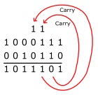
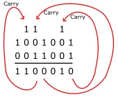
Adding binary numbers is easy if you remember that 1 + 1 = 0 with a carry of 1. If you're adding 1 + 1 + (a carry of 1), the sum is 1 with a carry of 1, in other words 1 + 1 + 1 = 1 with a carry of 1. Some examples are shown below.


These examples might be stored in a seven-bit registers. In the last example, a carry bit from the most significant bits goes beyond the seven bits that the register can hold. This carry bit would become an "overflow" bit and would be stored in a special "status" register that, when checked by the software would cause an "exception" that might cause the the results to go to a different format.
Subtracting Binary Numbers
Subtracting binary numbers might also be easy for humans, but it's easier to design logic circuits to add, so computers subtract by adding the two's compliment of the subtrahend. For example to subtract 0111 from 1001 you first have to convert 0111 to it's two's compliment.
To convert a number to its two's compliment, invert the number (change every 0 to a 1, and change every 1 to an 0) then add 1. Some examples are shown below.


In the last example, 23 - 29 results in a negative result. A value of 1 in the left-most cell, the sign bit, indicates that the register contains a negative number.
More Computer Architecture Articles:
• How Computer Memory Works
• Microcontroller Architectures
• Stored Program Architecture
• Digital Logic Semiconductor Families
• Introduction to Boolean Algebra
• Operating System Memory Protection in a Paged Environment
• Microcontrollers
• Processor Interrupts
• Shortest-Job-First CPU Scheduling Algorithm
• Digital Logic Transfer Characteristics

