

In many situations it is required that some program parameters, calibration tables, etc. are stored in nonvolatile memory, able to keep its contents indefinitely after the system is powered off.
The solution to this problem is to include in the structure of the microcontroller an EEPROM memory area. Most modern microcontrollers include between 128 bytes and 2 kilobytes of EEPROM.
For technological reasons, erasing and programming the EEPROM requires a 20 V Vpp (Voltage Peak-to-Peak ) voltage, obtained by means of a so-called charge pump. The current capability of this internal source is very low, and therefore the charge pump requires a time of around 10 milliseconds to stabilize. The following restrictions apply when accessing the EEPROM:
• Before programming, an EEPROM bit must be erased. The value of an erased bit is 1.
• After an erase or program operation, a 10-ms delay is required for the charge pump to stabilize.
The EEPROM Memory and the CONFIG Register of HC11
Depending on the model, the microcontrollers of the HC11 family have between 512 and 2048 EEPROM memory bytes, mapped in the general memory map. The starting address of the EEPROM memory area differs from one model to another, but, in some cases, the whole EEPROM block can be remapped, by means of the control bits [EE3:EE0] from the CONFIG register.
The Registers Controlling the EEPROM of HC11
The HC11 has two registers involved in the control of the EEPROM. These are the PPROG register (EEPROM Programming Control Register) and the BPROT register (EEPROM Block Protect Register). The PPROG register has the following structure:
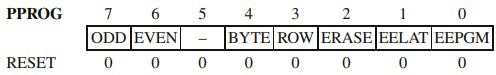
The ODD and EVEN bits are used in the special test operating mode and they will not be discussed here.
The BYTE, ROW and ERASE bits control the erase process of the EEPROM, according to Table 8.1.
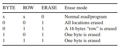
Table 8.1. The effect of programming the bits BYTE, ROW, and ERASE
• EELAT - EEPROM Latch Control bit
EELAT = 0 EEPROM address and data buses are prepared for normal read operations.
EELAT = 1 EEPROM address and data buses are prepared for write or erase operations.
Write operations to EEPROM with EELAT = 1 cause the values of address and data to be retained in special latches.
• EEPGM - EEPROM Program Control bit.
EEPGM = 1 starts the charge pump assuring the programming tension for the EEPROM.
The EEPGM bit can be written only if EELAT = 1.
The BPROT register has the following structure:
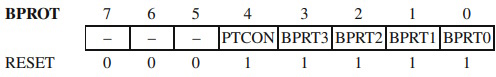
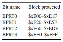
Table 8.2. Block addresses associated with BPRTi, valid for 68HC11F1
• PTCON - Protect CONFIG register. When this bit is set to 1, the CONFIG register
cannot be written or erased.
• BPRT3-BPRT0 - When these bits are 1, the protection of an EEPROM memory
block associated with each bit is activated, as shown in Table 8.2.
The BPROT register can only be written during the first 64 E cycles after RESET. Out of RESET, all BPROT bits are set to 1, which means that the protection is activated. The programming examples presented in the next paragraph assume that all bits of interest in the BPROT register have been erased in the initialization sequence, executed immediately after RESET.
The CONFIG Register
The CONFIG register consists of eight EEPROM cells, organized as a register located in the I/O register block of the MCU. The CONFIG register can be erased or programmed just like any other EEPROM location. The structure of the CONFIG register of 68HC11F1 is as follows:
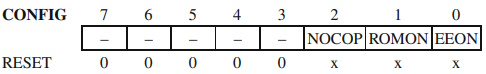
• NOCOP = 1 disables the COP (Computer Operating Properly) watchdog,
• ROMON = 1 enables the internal ROM.
• EEON = 1 enables the internal EEPROM
Some members of the HC11 family allow remapping of the EEPROM block to the beginning of any 4 K boundary in the memory map. To this purpose, the most significant four bits of the CONFIG registers, called [EE3:EE2:EE1:EE] are used to define the most significant four bits of the address of the EEPROM. For example, if [EE3:EE2:EE1:EE] = [0:1:0:1], then the starting address of the EEPROM is $5000.
The EEPROM Memory of the AVR Microcontrollers
There are significant differences in the way the EEPROM memory is implemented in AVR microcontrollers, compared to HC11. While in HC11, the EEPROM memory is directly visible in the memory map, and can be used as data memory or as program memory, for the AVRs the access to the EEPROM looks more like accessing data from a peripheral interface.
The Registers of the Interface with the EEPROM Memory
Four registers control the access to the EEPROM. These are named EEARH, EEARL, EEDR and EECR.
• EEARH - EEARL (EEPROM Address Register High/Low) form together a 16-bit
register that implements the EEPROM address space.
• EEDR - EEPROM Data Register. This is used to access the EEPROM data,
during the read and write operations.
• EECR - EEPROM Control Register contains the control bits for the write and
read operations. EECR has the following structure:
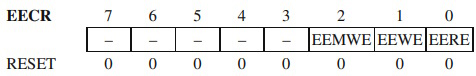
• EEMWE - EEPROM Master Write Enable. This bit provides a protection mechanism of the EEPROM data, in case of program runaway. The EEMWE is set by software, but is automatically cleared by hardware, after four cycles of the main system clock. In this interval of four cycles, it is possible to initiate a write operation to the EEPROM, by writing 1 to EEWE. Attempts to write to EEWE when EEMWE = 0 have no effect. EEWE is cleared by hardware when the write operation completes, usually after 2.5-4 ms, depending on the value of the supply voltage. Therefore, it is recommended to poll EEWE, to determine the end of the write operation.
• EERE - EEPROM Read Enable. This bit selects the access type to the EEPROM.
EERE = 1 indicates a read operation, while EERE = 0 indicates a write operation.
About Microcontrollers in Practice

The book is structured into three sections. Chapters 1-8 aim to create a detailed overview of microcontrollers, by presenting their subsystems starting from a general functional block diagram, valid for most microcontrollers on the market. In each case, we describe the distinctive features of that specific subsystem for HC11, 8051 and AVR. This whole section has a more theoretical approach, but, even here, many practical examples are presented, mainly regarding the initializations required by each subsystem, or the particular use of the associated interrupts. The purpose of this section is to create a perspective that views the microcontroller as a set of resources, easy to identify and use.
Chapters 9-16 contain eight complete projects, described from the initial idea, to the printed circuit board and detailed software implementation. Here too, we permanently focus on the similarities between the microcontrollers discussed, from the hardware and software perspectives.
All chapters contain exercises, suggesting modifications or improvements of the examples in the book. Most exercises have solutions in the book; for the others the solutions can be found on the accompanying CD.
Finally, the appendices contain additional information intended to help the reader to fully understand all the aspects of the projects described in the previous sections. We chose to present these details separately in these appendices, in order to avoid fragmentation of the flow of the main text.
Stressing common characteristics and real applications of the most used microcontrollers, this practical guide provides readers with hands-on knowledge of how to implement three families of microcontrollers (HC11, AVR, and 8051). Unlike the rest of the ocean of literature on individual chips, Microcontrollers in Practice supplies side-by-side comparisons and an overview that treats the systems as resources available for implementation. Packed with hundreds of practical examples and exercises to foster mastery of concepts and details, the guide also includes several extended projects. By treating the less expensive 8-bit and RISC microcontrollers, this information-dense manual equips students and home-experimenters with the know-how to put these devices into operation. Click here to learn more.

More Computer Architecture Articles:
• Expanding the Resources of Microcontrollers
• Intoduction to Digital Electronics
• Load Balancing Multiple CPUs in Symmetric Multiprocessing
• Monolithic Kernel vs Microkernel vs Hybrid Kernel
• Operating System Services
• Microcontroller's Parallel I/O System
• The Computer's Chipset
• Dynamic Loading of Program Routines and Dynamically linked libraries (DLLs)
• CPU Chip Packaging
• Program Flow Charting