One of the primary functions performed by a computer is mathematics. Even functions like graphics and sorting data are mathematics - because everything on a computer is represented by digital data. This article describes the digital logic circuits used to perform binary addition and subtraction.

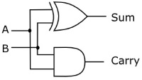
| A | B | Sum | Carry |
| 0 | 0 | 0 | 0 |
| 0 | 1 | 1 | 0 |
| 1 | 0 | 1 | 0 |
| 1 | 1 | 0 | 1 |
The circuit shown above and its accompanying logic diagram performs the function of adding two one-bit binary numbers. The output of the circuit provides the sum along with a possible carry. When adding higher-bit binary numbers however, provisions for a carry-in from a previous stage must be provided. For this reason, this circuit is called a "half-adder".

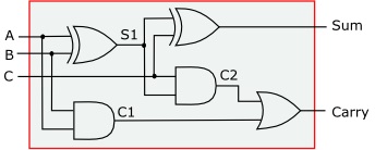
In the circuit shown above, a second stage has been added to accept a carry-in from a previous stage. The carry-out of this circuit is created by ORing the carry bits of both stages. This circuit is called a "full-adder".
| A | B | C | Sum | Carry |
| 0 | 0 | 0 | 0 | 0 |
| 0 | 1 | 0 | 1 | 0 |
| 1 | 0 | 0 | 1 | 0 |
| 1 | 1 | 0 | 0 | 1 |
| 0 | 0 | 1 | 1 | 0 |
| 0 | 1 | 1 | 0 | 1 |
| 1 | 0 | 1 | 0 | 1 |
| 1 | 1 | 1 | 1 | 1 |
Logic diagram of the full adder.

To simplify circuit diagrams we could indicate a full adder using a simple box labeled with the circuit's function and with its inputs and outputs labeled.

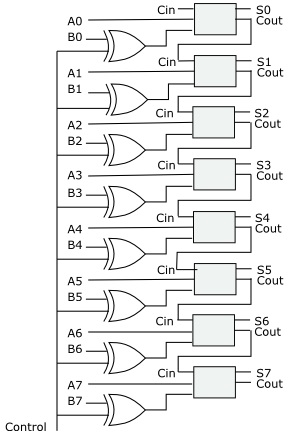
By connecting eight full-adder circuits together, each circuit's carry-out output to the carry-in input of the next circuit, we can construct an eight-bit binary adder.

| A | Control | Out |
| 0 | 0 | 0 |
| 1 | 0 | 1 |
| 0 | 1 | 1 |
| 1 | 1 | 0 |
Shown above is an exclusive OR (XOR) gate and it's logic table, except this time we labeled one of its inputs Control. Note that when the control input is low (binary 0), the output is the same as the binary value on the A input. When the control input is high (binary 1), the output is the inverted value of the A input. What we have here is a controllable inverter. In other words with 0 on control, the input passes though unchanged, with 1 on control, we have an inverter.

As previously described, in binary mathematics, subtracting a number is accomplished by instead adding the two's complement of the number. In the circuit shown above we run every bit of the second number of a binary math operation through a controllable inverter. If we wish to add the two numbers, we put 0 on the control line. If we wish to subtract the second number we put 1 on the control line. (In actual operation we would need to add 1 to the inverted number before adding).
This article describes some of the logic circuits used to create the Arithmetic Logic Unit (ALU) of a microprocessor.
More Computer Architecture Articles:
• The Computer's Chipset
• Logical Versus Physical Memory Addresses
• Operating System File Management
• Binary Floating-Point Numbers
• Processor Interrupts
• Binary Number Representation and Binary Math
• Microcontroller Architectures
• The Evolution of Hard Disk Bit Recording
• Direct Memory Access (DMA)
• Digital Logic Transfer Characteristics

